Physics › Required practicals › EMF and internal resistance of a cell
REQUIRED PRACTICAL 6EMF and internal resistance of a cell
Measuring how the terminal potential difference of a cell falls as the current drawn from it rises, and extracting the emf and internal resistance.
Theory: EMF and internal resistance
What you are trying to do
Measure how a cell's terminal pd falls as the current drawn from it rises, and extract the emf and internal resistance from the graph.
Apparatus
- The cell under test, in a holder
- Variable resistor to set the current
- Ammeter in series, voltmeter across the cell's terminals
- A switch, kept open except while reading
Variables
- Independent: the current, set by the variable resistor
- Dependent: the terminal pd
- Control: the cell itself: temperature and state of charge, protected by keeping the switch open between readings
Method
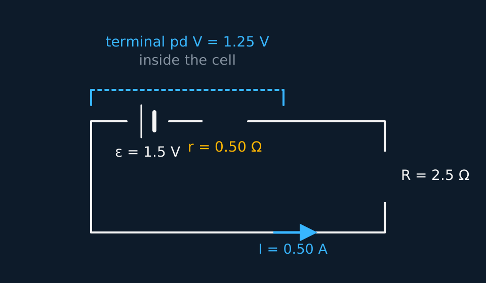
- Set the variable resistor for a small current, close the switch, read both meters quickly, open the switch again.
- Step the resistance down to raise the current, covering as wide a current range as the cell sensibly allows, and repeat the sweep to check for drift.
Analysis
- The loop equation V = ε − Ir is already straight-line shaped: plot V against I.
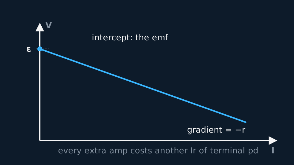
- Read ε from the intercept and r from the gradient, quoting r positive and noting the gradient is negative.
- What the two numbers are worth. They are not equally secure. The emf is read where you took no readings at all, so it rests on the line you drew, while the internal resistance comes from the slope of a pd that moves by only a few tenths of a volt across the whole sweep. A cell returning about 1.5 V and half an ohm supports the model over the currents you used and says nothing about five amps, where a cell warms and its internal resistance need not stay constant. There is a second route to the emf worth taking: a voltmeter alone across the cell draws a current small enough to ignore provided its input resistance is very much larger than the cell's internal resistance, and its reading should then agree with your intercept.
- What the method cannot follow. The model assumes ε and r remain approximately constant. Heating, polarisation or discharge can make them drift, and the points may still fall on a line while they do, so the graph alone will not show it. Repeat the current sweep in reverse order; failure to retrace indicates time-dependent behaviour.
A worked set of readings
One sweep, switch closed only to read:
| I / A | V / V |
|---|---|
| 0.20 | 1.40 |
| 0.40 | 1.30 |
| 0.60 | 1.20 |
| 0.80 | 1.10 |
| 1.00 | 1.00 |
Idealised illustrative data, chosen so the working is easy to follow. Real readings scatter about the line rather than sitting on it, and your own graph will have points either side of the best fit.
The line has gradient −0.50 V A⁻¹ and V-axis intercept 1.50 V, so ε = 1.50 V and r = 0.50 Ω. Every row agrees: for instance 1.20 + 0.60 × 0.50 = 1.50 V.
Evaluating the result
Idealised readings, swept once and then swept again. During the first sweep the switch was left closed at 0.80 A while the reading was discussed. Sustained current warms the cell and its terminal pd falls. The second sweep repeats the same currents with the switch closed only long enough to read both meters.
| I / A | V, first sweep / V | V, second sweep / V |
|---|---|---|
| 0.20 | 1.40 | 1.40 |
| 0.40 | 1.30 | 1.30 |
| 0.60 | 1.20 | 1.20 |
| 0.80 | 1.05 | 1.10 |
| 1.00 | 1.00 | 1.00 |
Idealised illustrative data, chosen so the working is easy to follow. Real readings scatter about the line rather than sitting on it, and your own graph will have points either side of the best fit.
Every pair agrees except at 0.80 A, where the first sweep reads 0.05 V low and the second sits back on the line. What identifies the reading is not that it looks wrong but that it does not repeat. Keeping it would pull the high-current end down, steepening the line and increasing the value of r while barely moving the intercept, so the error would land on the quantity that is hardest to check independently. Use the repeated sweep, keep both sets of readings in the table, and record why the first reading at that current was excluded.
Where the uncertainty comes from
- The cell running down: Sustained current warms the cell and depletes it, drifting both ε and r mid-experiment; the open-switch habit is the control that matters most.
- Meter resolution: The terminal pd changes by fractions of a volt across the whole sweep; a digital voltmeter's 0.01 V resolution is what makes the gradient readable.
- Extrapolation: The intercept lies beyond the smallest measurable current, so the emf rests on extrapolating the line; a wide current range anchors it.
- Ammeter position: The ammeter's own small resistance sits in the loop but outside the voltmeter's connections, so it acts as part of the external load and does not upset the relation between the measured V and I.
- Voltmeter loading: The voltmeter draws a current of its own, which the analysis ignores. That is acceptable only when its input resistance is very much larger than the cell's internal resistance; state the meter's input resistance if you rely on the assumption.
What earns the marks
✓Marks
- The switch stays open between readings, and the reason is thermal and chemical drift of the cell.
- Identify the V-axis intercept as ε and the gradient as minus r, and say why each follows from V = ε − Ir.
- The terminal pd equals the emf only at zero current; a voltmeter of sufficiently high input resistance connected alone across the cell therefore reads very nearly ε.
- Quote r as a positive resistance with the gradient stated negative.
Safety
!Caution
Low voltages throughout; the only real hazard is a near-short at the lowest resistance settings, which heats the cell and the rheostat. Keep currents modest and the switch open when not reading.
Method and analysis here follow the standard approach; your school may vary the apparatus. Always follow your teacher’s risk assessment in the lab.