Physics › Required practicals › Force on a current-carrying wire
REQUIRED PRACTICAL 10Force on a current-carrying wire
Using a top-pan balance to measure how the force on a wire depends on the magnetic flux density, the current and the length in the field.
Theory: Magnetic flux density and the force on a wire
What you are trying to do
Measure the force on a current-carrying wire in a magnetic field with a top-pan balance, and test F = BIl.
Apparatus
- A pair of magnadur magnets on an iron yoke, standing on a top-pan balance reading to 0.01 g
- A stiff copper wire clamped rigidly so it passes horizontally between the poles without touching them
- DC supply, ammeter and rheostat; a switch
- A rule to measure the length of the magnet region
Variables
- Independent: the current in the wire
- Dependent: the force, read as the change in the balance reading
- Control: the field (same magnets), the length in the field, and the geometry: wire horizontal and at right angles to the field
Method
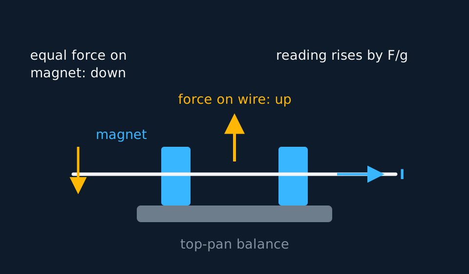
- Zero (tare) the balance with the wire in place and the current off.
- Switch on, read the change in the balance reading, switch off. Repeat at a series of currents, and reverse the current at each one: the magnetic contribution reverses with it, while a mechanical offset does not, so half the difference between the two readings is the magnetic force alone.
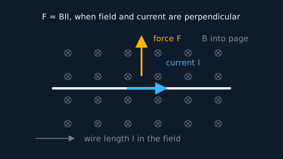
- Measure the magnet length and take it as an approximation to the effective length of wire in the field: the field falls away quickly, though not sharply, beyond the poles.
Analysis
- The balance reads mass, so convert: F = Δm × g, with Δm in kilograms.
- Plot F against I and fit a straight line without forcing it through the origin. The gradient is Bl, so the flux density is the gradient divided by the measured length. A non-zero intercept indicates a tare or mechanical offset rather than a magnetic force.
- What one straight line tests. A straight F against I line with no significant intercept, and a gradient giving a flux density of the right size for magnadur, supports the current dependence in F = BIl. It leaves the length and the angle untested, because both were held fixed. To test length dependence, use two or three parallel wire segments in the field, ensuring that the current directions are the same so their forces add, and check that the force follows the number of segments.
- What the balance is really weighing. It reads a vertical force and cannot tell a magnetic one from a stiff lead pressing on the yoke or a draught across the pan. Reversing the current separates the two: the magnetic contribution changes sign while a mechanical offset does not. The balance also reports a force spread over a length that is not sharply defined, since the field fringes past the ends of the magnets, so the l you divide by is a little shorter than the length the current actually feels, and B comes out a little high. Repeating readings does nothing for either. A Hall probe in the gap gives an independent B, which is the check that settles it.
A worked set of readings
Magnadur pair of length 5.0 cm; balance tared at zero current:
| I / A | Balance change / g | F / mN |
|---|---|---|
| 1.0 | 0.41 | 4.0 |
| 2.0 | 0.82 | 8.0 |
| 3.0 | 1.22 | 12.0 |
| 4.0 | 1.63 | 16.0 |
| 5.0 | 2.04 | 20.0 |
Idealised illustrative data, chosen so the working is easy to follow. Real readings scatter about the line rather than sitting on it, and your own graph will have points either side of the best fit.
The gradient of F against I is 4.0 mN A⁻¹, which is Bl. Dividing by l = 0.050 m gives B = 0.080 T, a typical magnadur field.
Evaluating the result
Idealised readings with one taken while a lead rested on the yoke. Changing the current means moving leads, and a stiff wire leaning on the magnet assembly presses on the balance exactly as a magnetic force would. The third column divides F by I, which the model says is Bl and the same at every current.
| I / A | F / mN | F/I / mN A⁻¹ |
|---|---|---|
| 1.0 | 4.00 | 4.00 |
| 2.0 | 8.00 | 4.00 |
| 3.0 | 12.90 | 4.30 |
| 4.0 | 16.00 | 4.00 |
Idealised illustrative data, chosen so the working is easy to follow. Real readings scatter about the line rather than sitting on it, and your own graph will have points either side of the best fit.
Three rows return 4.00 mN A⁻¹ and the disturbed one returns 4.30. Reversing the current distinguishes the explanations. A magnetic force changes sign, so the balance reading should change by the same amount in the opposite direction, while a lead resting on the yoke presses the same way whichever way the current runs. If the two readings are not equal and opposite, the difference between them is mechanical: dress the leads so they hang free and repeat that current. Keep the original readings in the table with the reason recorded, even when a point is excluded from the fit.
Where the uncertainty comes from
- The field's edges: The field is not a sharp box: it fringes beyond the magnets, so the effective length is slightly more than the magnet length. This is usually the dominant systematic.
- Balance resolution: 0.01 g is a tenth of a millinewton; small currents produce changes only a few times that, so the graph leans on the larger currents.
- Geometry: F = BIl sin θ, where θ is the angle between the wire and the field, so the force is greatest with the wire perpendicular to the field; clamp the wire square and horizontal.
- Heating: A current of several amps warms the wire; switch off between readings.
What earns the marks
✓Marks
- State the Newton's third law step: the balance reads the force on the magnets, equal and opposite to the force on the wire.
- Convert the balance change to newtons with g, in SI units.
- Gradient of F against I is Bl; divide by l for B.
- Reversing the current reverses the magnetic force, so a reading that does not reverse is mechanical or thermal rather than magnetic.
Safety
!Caution
Currents of several amps heat the wire and drain supplies: switch on only to read. Keep the balance and yoke stable, and keep steel objects away from the magnets.
Method and analysis here follow the standard approach; your school may vary the apparatus. Always follow your teacher’s risk assessment in the lab.