Physics › Electricity › Series, parallel and power
Series, parallel and power
Series components share one current and their resistances add; parallel branches share one pd and the reciprocals of their resistances add. The shared quantity picks the power equation too, I²R for components in series and V²/R for branches in parallel, with E = IVt for the energy transferred.
Choose your exam board to show the notes and questions relevant to your specification. You can change this setting at any time, and content for other boards remains available.
Watch Series, parallel and power on the InkPhysics YouTube channel
Circuits and Kirchhoff's laws, part 2 of 2. Part 1 is Circuit symbols and Kirchhoff's laws.
Builds on Circuit symbols and Kirchhoff's laws.
IN THIS TOPIC
- Handle the series and parallel rules for current, pd and resistance, cells in series and identical cells in parallel included.
- Analyse a circuit carrying more than one source of e.m.f., adding the emfs that drive the same way round and subtracting the one that opposes.
- Pick the right energy or power equation, E = IVt and the three forms of P, from what the circuit shares.
COMMON MISCONCEPTION
Adding another resistor always makes a circuit harder for the current to get through.
It depends where you add it. In series the resistances add, so the total rises. In parallel the added branch is another road for the charge, so more current flows for the same pd and the combined resistance falls below even the smallest branch.
Series circuits
A series loop provides one path only, so by conservation of charge the same current flows at every point. An ammeter reads the same value wherever it is inserted in the loop, which is why current is not used up on the way round.
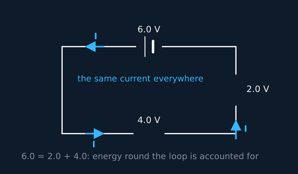
Conservation of energy round the loop means the pds across the components add up to the supply's emf. Divide that statement by the shared current and the resistance rule appears.
Cells in series behave the same way. Their emfs add, so two 1.5 V cells make a 3 V battery.
Parallel circuits
Parallel branches connect the same two points, so every branch has the same pd across it. By the junction rule the current divides between the branches and recombines, and the branch currents add to the total.
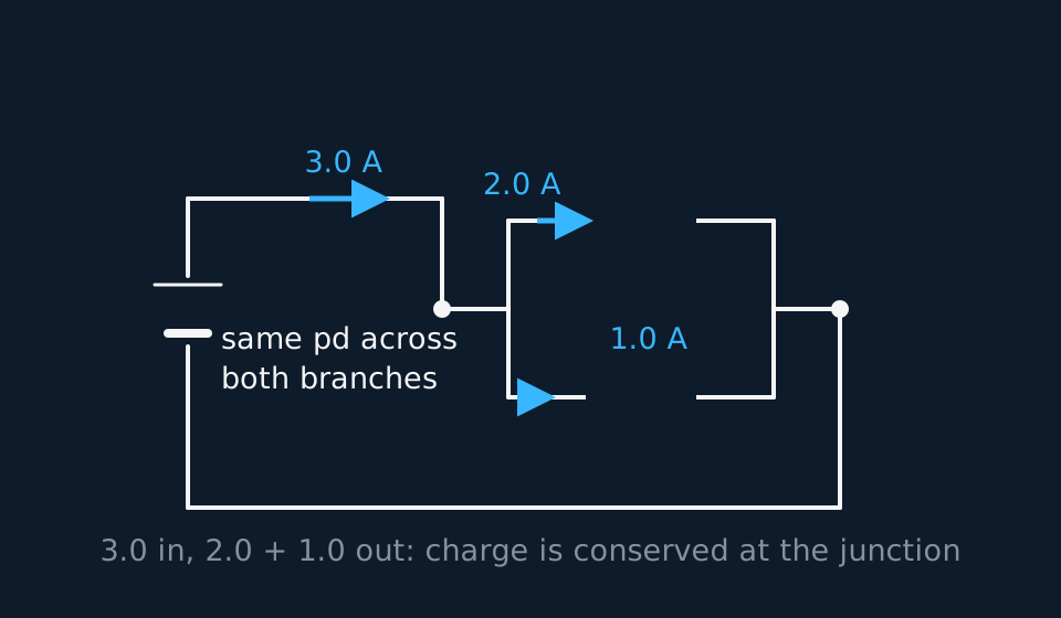
Adding the branch currents at the shared pd gives the resistance rule.
Adding a parallel branch provides another path for current and therefore reduces the combined resistance below the resistance of either branch, so a parallel combination is always smaller than its smallest branch. Identical cells in parallel give the emf of a single cell, no more, but they share the current between them, so each supplies less current and the battery lasts longer.
WORKED EXAMPLE
Combining a parallel pair
Find the combined resistance of 12 Ω and 6.0 Ω in parallel.
For two resistors, product over sum is quickest. R = (12 × 6.0)/(12 + 6.0) = 72/18 = 4.0 Ω.
Check it against the rule for parallel combinations. A parallel combination always comes out smaller than the smallest branch, and 4.0 Ω sits below 6.0 Ω.
An answer of 18 Ω (the sum) or 9 Ω (the average) fails that check, so apply it to every parallel combination.
More than one source in the loop
Neither law is restricted to a single source. Conservation of energy round a loop is a statement about joules per coulomb: the emfs met around the loop, taken with their signs, equal the pds across the components around the same loop. The sign of each emf is set by the terminal reached first. A source entered at its negative terminal and left at its positive terminal transfers energy to the charge, so its emf is positive; a source traversed the other way takes energy from the charge, so its emf is negative.
Two cells connected so that both drive the same way round the loop therefore add, which is why two 1.5 V cells give 3.0 V. Reverse one of them and it opposes the other, so the loop is driven by the difference of the two emfs. A cell driven backwards by a larger emf is being charged: the energy transferred to it is stored chemically rather than dissipated, so it is accounted for as an εI term and not as an I2R term.
WORKED EXAMPLE
A charger and the battery it is charging
A 12 V charger is connected to a 9.0 V rechargeable battery with their emfs opposing, through a 3.0 Ω protective resistor. Find the current, and say where the charger's power goes.
The two emfs oppose, so the loop is driven by 12 − 9.0 = 3.0 V, and that is the only pd available to push a current through the resistor.
I = 3.0/3.0 = 1.0 A, driven in the direction set by the net emf, so it enters the battery at its positive terminal. That is the direction that charges it.
Now the power. The charger supplies IV = 1.0 × 12 = 12 W. The resistor dissipates I2R = 1.0 × 3.0 = 3.0 W, and the remaining 9.0 W, equal to 9.0 V × 1.0 A, is stored chemically in the battery. Dividing that power balance by the current gives Kirchhoff's second law for this loop.
Sources in different branches need one more step. If two cells, each with its own resistor, feed a shared load, no single series or parallel rule applies. Label an unknown current in each branch, use the junction rule to write the third current as the sum of the other two, and write one loop equation for each independent loop. That gives as many equations as unknowns.
GUIDED PRACTICE
Two unequal cells, one load
A 6.0 V cell in series with a 1.0 Ω resistor and a 3.0 V cell in series with a 1.0 Ω resistor are wired side by side across a shared 2.0 Ω load. Taking I1 and I2 out of the 6.0 V and 3.0 V branches, find both currents and the pd across the load.
Show the working
The junction rule sends I1 + I2 through the load, so its pd is V = 2.0(I1 + I2). Each branch then gives a loop equation: 6.0 = 1.0I1 + V and 3.0 = 1.0I2 + V.
Substituting I1 = 6.0 − V and I2 = 3.0 − V into the first line gives V = 2.0(9.0 − 2V), so 5V = 18 and V = 3.6 V.
Then I1 = 2.4 A and I2 = −0.6 A. The negative sign means the current in that branch runs opposite to the direction assumed: 0.6 A flows into the 3.0 V cell, which the 6.0 V cell charges while driving 1.8 A through the load. An assumed direction need not be correct, because the sign of the answer corrects it.
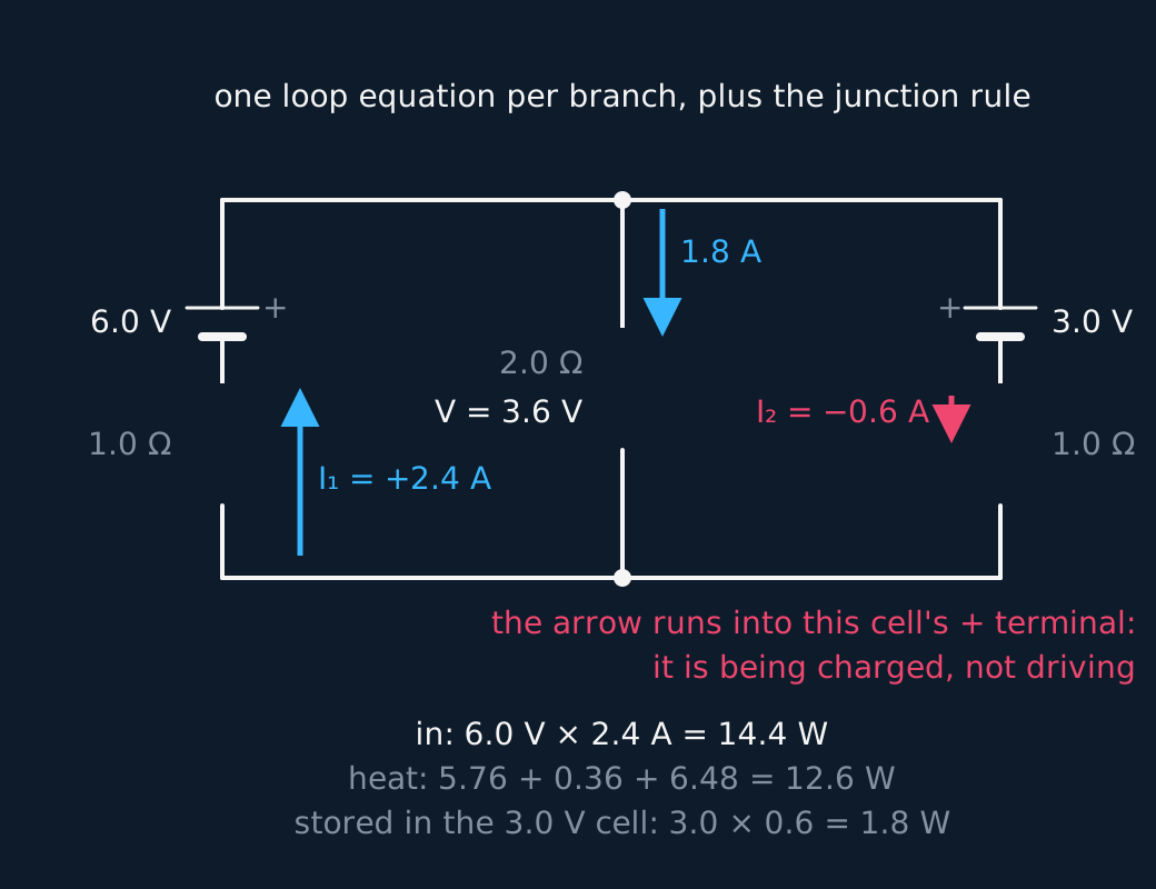
Two limitations of this model. The larger emf drives current backwards through the smaller source whether or not that source is rechargeable; a dry cell that cannot be charged transfers the energy to internal energy instead. Real sources also have an internal resistance that a circuit diagram does not show, which is covered in the lesson on emf and internal resistance.
Energy and power
A pd of V drives energy through a component at a rate set by the current. Over a time t the energy transferred is
and the rate of transfer, the power, comes in three interchangeable forms via R = V/I:
Choose the form built from the quantity the arrangement shares. Series components share the current, so compares them directly and the largest resistance dissipates the most power. Parallel branches share the pd, so applies and the smallest resistance dissipates the most power. The two conclusions differ because the shared quantity differs.
GUIDED PRACTICE
Inside a kettle's rating plate
A kettle is rated 3.0 kW at 230 V. Choose the power equation that uses the quantities given, then find the element's resistance and the current drawn.
Show the working
P and V are what you have, so use P = V2/R. That gives R = 2302/3000 = 18 Ω.
Then I = P/V = 3000/230 = 13 A, close to the 13 A rating of a domestic plug fuse. Selecting the equation that already contains the given quantities avoids an unnecessary rearrangement.
INDEPENDENT PRACTICE
The same heaters, rewired
Two identical 6.0 Ω heating elements, whose resistance you may take as constant, are connected to a 12 V supply, first in series, then in parallel. Find the power of each element in both arrangements.
Show the working
In series the total is 12 Ω, so 1.0 A flows everywhere and each element dissipates I2R = 1.0 × 6.0 = 6.0 W.
In parallel each element sees the full 12 V, so each dissipates V2/R = 144/6.0 = 24 W.
The parallel arrangement gives four times the power, and that factor depends on the resistance being constant. Filament lamps are not constant-resistance components: a filament running cooler in series has a lower resistance, so real lamps in series dissipate more than a quarter of the parallel power, although parallel still gives much more. Household wiring is parallel for this reason, and series-wired lamps all go out when one filament breaks.
ASSESSMENT FOCUS
- A parallel combination comes to less than its smallest branch. If an answer is larger than that, check the final reciprocal, which is the step most often omitted.
- With two sources in one loop, establish their directions first. Emfs driving the same way round add and opposing emfs subtract, and the current flows in the direction set by the net emf. A source that the current is driven backwards through stores energy rather than dissipating it, so account for it with an εI term rather than an I2R term.
- When sources sit in different branches, no series or parallel simplification applies. Name a current in each branch, use the junction rule once, then write one loop equation per loop and solve. A negative answer means the assumed direction was reversed.
- Choose the power form by the shared quantity: series shares I, so use ; parallel shares V, so use .
- The data sheet gives the power forms. E = IVt is obtained from power × time, and is one to learn.
- AQA does not set circuits that require simultaneous equations for the currents. If the working reaches that point, look again for a series or parallel simplification.
CHECK YOURSELF
A 6.0 Ω and a 3.0 Ω resistor are connected in parallel, and the pair is in series with a 4.0 Ω resistor across a 12 V supply. Find the current drawn from the supply and the pd across the parallel pair.
Show a hint
Collapse the parallel pair first, then treat the circuit as a simple series loop.
Show the answer
Parallel pair first. gives R = 2.0 Ω, smaller than either branch, as it must be.
Total resistance is now 2.0 + 4.0 = 6.0 Ω, so the supply delivers I = 12 / 6.0 = 2.0 A.
Across the pair, V = IR = 2.0 × 2.0 = 4.0 V, leaving 8.0 V across the 4.0 Ω resistor. The two pds add to the 12 V supply, as Kirchhoff's second law requires.
Series shares the current.
Parallel shares the pd.
Adding a parallel branch provides another path for current, so the combined resistance falls below the resistance of either branch.
Or read them with their mark schemes on the circuit symbols and kirchhoff's laws questions page.
CHECK YOUR PROGRESS
Rate how confident you feel with each objective for this lesson. Ratings are saved in this browser, on this device, unless you sign in.
- Handle the series and parallel rules for current, pd and resistance, cells in series and identical cells in parallel included.
- Analyse a circuit carrying more than one source of e.m.f., adding the emfs that drive the same way round and subtracting the one that opposes.
- Pick the right energy or power equation, E = IVt and the three forms of P, from what the circuit shares.
Open the full revision checklist to track your progress across the whole unit.