PhysicsElectricity › Potential dividers

Potential dividers

Two resistors in series turn one supply voltage into any smaller voltage you like, set purely by a ratio. Swap one resistor for a thermistor or an LDR and that same ratio turns temperature or light into a voltage a circuit can act on.

Builds on Circuits and Kirchhoff's laws.

IN THIS TOPIC

  • Explain why series resistors share the supply pd in the ratio of their resistances.
  • Calculate a divider's output, and supply a variable pd with a sliding contact.
  • Describe how the potential varies along a uniform current-carrying wire, and take a pd off a length of it.
  • Predict what connecting a load across the output does to that output, and how to keep the effect small.
  • Design sensing dividers from thermistors and LDRs, choosing which resistor carries the output.
  • For CIE, compare potential differences on a potentiometer, and say what the galvanometer does in a null method.

COMMON MISCONCEPTION

The battery decides the voltage across each component.

Sharing in the ratio of the resistances

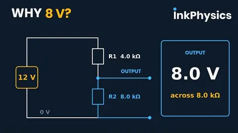
Put two resistors in series across a supply and one current threads both of them. Each takes a pd of V = IR, so the shares come out proportional to the resistances. The battery fixes only the total; the resistors negotiate the split between themselves. Taking the output across R2 gives

Vout=Vin×R2R1+R2V_{out} = V_{in} \times \frac{R_{2}}{R_{1} + R_{2}}NOT ON THE AQA DATA SHEET: LEARN IT
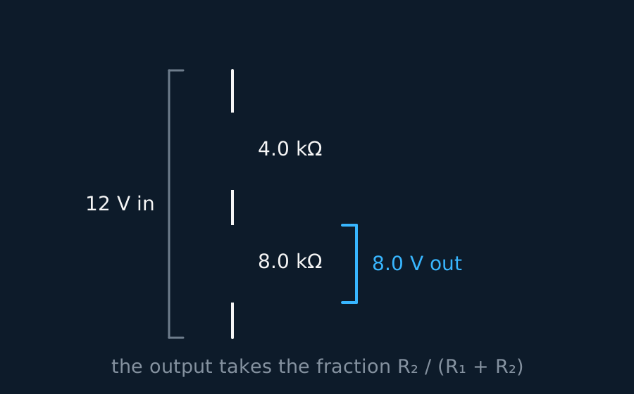
A potential divider: two resistors in series share the input pd in the ratio of their resistances4.0 kΩ8.0 kΩ12 V in8.0 V outthe output takes the fraction R₂ / (R₁ + R₂)
FIG. 1A 12 V supply across 4.0 kΩ and 8.0 kΩ in series. The 8.0 kΩ resistor holds two thirds of the resistance, so it takes two thirds of the pd: 8.0 V.

Sanity-check the formula at its limits. Shrink R2 to nothing and the output falls to zero; grow it without bound and the output climbs towards the full supply. Any voltage between those two is available, provided the output feeds something that draws almost no current; connect a real load and the output sags, which is the subject of its own section below.

A dial for voltage

Make the split point movable and the divider becomes adjustable. A sliding contact on a resistance track divides it into two parts whose ratio changes as the contact moves, so the output follows the slider, continuously, from zero to the full supply.

The potential divider: a dial that behaves (animated figure)slide the wiper; the output follows6.0 V supplyresistive track6 V3 V0output p.d.
FIG. 2A potential divider with a sliding tap. The wiper glides along the resistive track and the output p.d. is simply the share of the 6.0 V below the tap. Slide high, nearly six volts; slide low, nearly none: a voltage you can dial.

Volume knobs, dimmer switches and joystick axes are all built this way, on one track and one wiper.

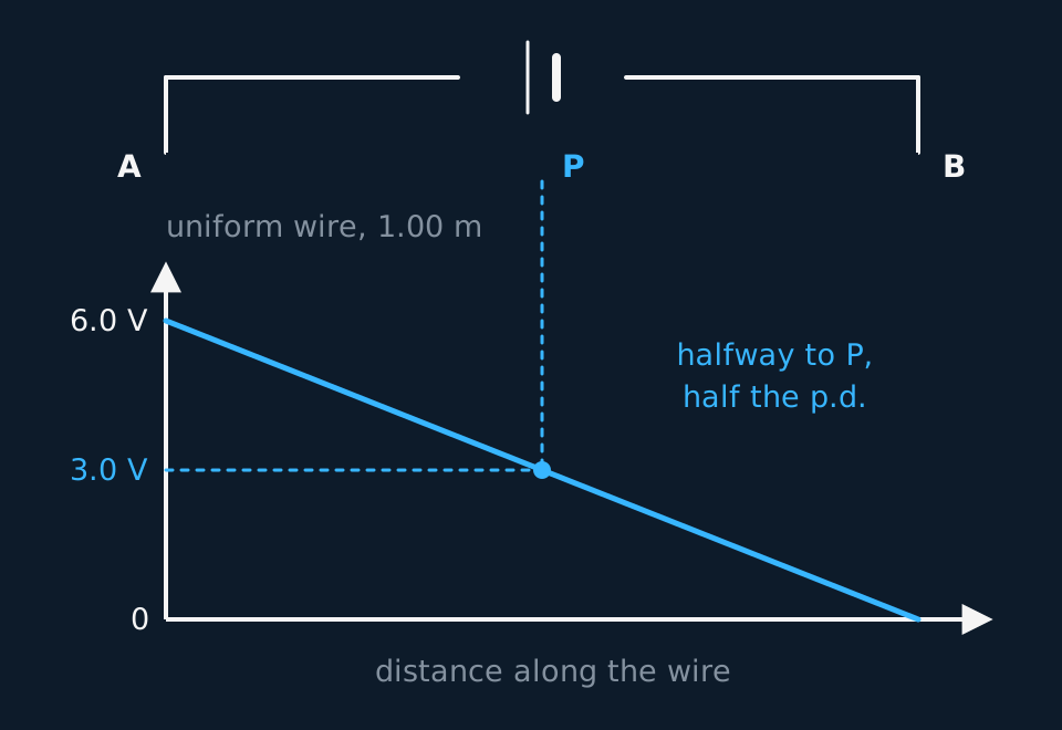
Make that track a uniform wire, one material at one cross-section for its whole length, and the dial acquires a scale. A single current threads the wire end to end, and R = ρL/A gives every centimetre of it the same resistance, so every centimetre takes the same pd. The potential therefore falls at a steady rate along the wire, from the full supply at the end joined to the positive terminal down to zero at the far end, and the pd across any part of it is proportional to the length of that part. Writing V for the pd across the whole length L, the pd Vx across a length x measured from the far end is
Vx=VxLV_{x} = V\frac{x}{L}
The potential along a uniform current-carrying wire falls in a straight line with distanceABuniform wire, 1.00 mP6.0 V3.0 V0halfway to P,half the p.d.distance along the wire
FIG. 3A metre of uniform wire carrying a steady current, and beneath it the potential plotted against distance along it: a straight line from 6.0 V down to zero, so the halfway point sits at 3.0 V.

Plot potential against distance and the graph is a straight line, whose gradient is the potential gradient along the wire, in volts per metre. Halfway along is half the pd, a fifth of the way along is a fifth of it, and that proportionality is the reason a wiper on a uniform track reads off the fraction of the way it has travelled. It also makes a wire laid beside a metre rule into a voltage scale, which is what the closing section of this lesson puts to work.

WORKED EXAMPLE

Designing for five volts

A circuit needs 5.0 V from a 9.0 V supply. The lower resistor of the divider is 10 kΩ and the output is taken across it. Find the upper resistance required.

The output takes its share of the supply in the ratio of the resistances. Put 5.0 of the 9.0 volts across the bottom resistor and 4.0 V is left for the top.

One current threads both, so the resistances sit in the same 4.0 to 5.0 ratio as their voltages. Rtop = 10 × 4.0/5.0 = 8.0 kΩ.

Check by running the divider forward: 9.0 × 10/(10 + 8.0) = 5.0 V.

What a load does to the output

Everything so far has assumed the output goes nowhere, and that assumption is what a good question breaks. Connect a real component across the output and it sits in parallel with whichever resistor the output is taken across. The pair has a lower resistance than that resistor alone, so its share of the supply shrinks and the measured output sags below the value the ratio alone predicts.

Numbers show the scale of it. Two equal resistors give half the supply with nothing attached. Hang a load of the same resistance across the lower one and the output falls from half the supply to a third of it. Make the load ten times the divider resistance and the sag is only a few per cent.

So a design has two escapes, and either earns the mark. Build the divider from resistances well below whatever will be connected, or feed the output into something that draws almost no current, a high-resistance voltmeter or an amplifier input. Low divider resistances cost you a current running permanently through the chain, which matters in anything battery powered.

Sensing circuits

Replace one resistor with a component whose resistance responds to the world and the divider becomes a sensor. An ntc thermistor's resistance falls as it warms; a light dependent resistor (LDR) behaves the same way towards light, its resistance falling as the illumination rises. Either way, the changing resistance moves the ratio, and the output voltage tracks the environment.

A thermistor in a divider turns a temperature change into a voltage change, the outputs quoted here being the shares of a 6.0 V supply6.0 V supplythermistor2.0 kΩoutputcold: 10 kΩoutput 1.0 Vwarm: 1.0 kΩoutput 4.0 Vwarming shrinks the thermistor's share; the output rises
FIG. 4A thermistor above a fixed resistor, output across the fixed resistor. Warming collapses the thermistor's resistance and its share of the pd, so the output rises from 1.0 V to 4.0 V.

Design comes down to one decision, which resistor the output is taken across. Put the output across the fixed resistor and warming the thermistor raises it, the right way round for switching on a fan. Move the output to the thermistor and the response inverts, which suits a heater instead. The component senses; its position in the divider sets the direction of the change.

GUIDED PRACTICE

A light switch that switches itself

An LDR (100 kΩ in darkness, 1.0 kΩ in daylight) sits above a fixed 10 kΩ resistor across a 6.0 V supply, output across the fixed resistor. Find the output voltage in the dark and in the light.

Show the working

In the dark, Vout = 6.0 × 10/(100 + 10) = 0.55 V. In daylight, 6.0 × 10/(1.0 + 10) = 5.5 V.

A swing of ten times between night and day is plenty to trip a switching circuit. The divider has turned a resistance change into a voltage signal, which is the job of a sensing circuit.

The potentiometer and null methods, a CIE extension

One board takes the divider further. CIE asks for the potentiometer as a means of comparing potential differences, and for the part a galvanometer plays in a null method, so read this section only if CIE is your specification. OCR mentions the potentiometer as well, but only as the three-terminal potential divider you met with the sliding contact above. The uniform wire it is built on belongs in the main body above, and Edexcel asks for that much; what is CIE's alone is the null method laid on top of it.

The arrangement is that same metre of uniform resistance wire, now laid along a scale, with a driving cell across its ends keeping a steady current in it. The potential falls uniformly along it, so the pd between one end and any point is proportional to the length of wire between them. Tapping the wire at 65.0 cm of a 100.0 cm run driven at 2.00 V gives 1.30 V, and the wire has become a divider with a scale printed alongside it. The sliding contact earlier in this lesson supplied a pd you could dial; this one is a pd you are going to balance something against.

Now the measurement. Connect the cell you want to measure between that same end of the wire and a sliding contact, the jockey, with a galvanometer in the branch, and connect it so that its emf opposes the pd along the wire. Slide the jockey until the galvanometer reads exactly zero. That is the balance point, and at balance the two pds are equal and opposite, so the cell's emf equals the pd across the tapped length.

A potentiometer used as a null method: the jockey is slid until the galvanometer reads zeroABGJAJ = 65.0 cmthe cell being measuredthe driving cellslide until the galvanometer reads zero: no current is drawnand the cell's e.m.f. equals the p.d. across AJ, here 1.30 V
FIG. 5The null method in one picture. The driving cell keeps a steady current in the uniform wire AB; the cell being measured opposes the pd across AJ through a galvanometer. At the balance point the galvanometer reads zero, so the 65.0 cm of wire and the cell hold exactly the same pd.

The point of all that sliding is what happens at zero. No current flows in the branch, so the cell being measured drops no lost volts inside itself and you read its emf rather than its terminal pd. Nor does the branch load the wire, so the divider ratio is the plain length ratio. A voltmeter cannot do either of those things perfectly, because a real voltmeter has finite input resistance and so draws some current, tiny for a modern digital meter, larger for a moving-coil needle.

Comparing two potential differences is then a matter of two balance lengths. Balance one source at l1, swap it for the other, rebalance at l2, and divide.

E1E2=l1l2\frac{E_{1}}{E_{2}} = \frac{l_{1}}{l_{2}}

Everything about the driving circuit cancels, which is why the method is so hard to fool. It also means both balances must be taken with the driving circuit undisturbed, since a driving cell that runs down between the two readings changes the volts per centimetre and quietly breaks the comparison.

The galvanometer earns its place by being sensitive and centre-zero, and by needing no calibration whatsoever. You never read a value off it, only a zero, so any error in its scale drops out of the result, and its own resistance cannot shift where the balance sits, though it does set how sharply the balance is felt, since it decides how much current a given imbalance drives. That is what a null method means: the instrument locates a balance instead of measuring a quantity. Which side it kicks tells you which way to slide, and a kick the same way at both ends of the wire means the driving pd is smaller than the emf you are trying to balance, or the cell is in the wrong way round.

One practical warning about the drawing. The galvanometer above carries the circle-and-G used everywhere on this site, because one symbol set has to serve everyone reading these pages. The glyph printed on your own paper is the one that counts, so check the symbol list published with your specification and be ready to recognise the detector in whatever form it arrives.

WORKED EXAMPLE

Comparing two cells

On a 100.0 cm potentiometer wire, a standard cell of emf 1.018 V balances at 50.9 cm. An unknown cell, measured with the same driving circuit, balances at 32.5 cm. Find its emf.

The wire is uniform, so the pd tapped off is proportional to the balance length, and the two emfs sit in the ratio of the two lengths.

E2 = 1.018 × 32.5/50.9 = 0.650 V.

Notice what never entered the working. Not the driving emf, not the current in the wire, not the resistance of anything. Two lengths and one known cell, which is why the potentiometer was the standard laboratory way of measuring an emf long before digital meters existed.

ASSESSMENT FOCUS

  • Read the circuit before you write the formula. The numerator is the resistance the output is taken across, over the total, and assuming it is always the bottom resistor is a planted trap.
  • Track the share as well as the resistance. Warm a thermistor and its resistance falls, its share of the supply falls with it, and the other resistor's share rises. Any output across that other resistor rises too.
  • State the LDR's direction in words. Resistance falls as light intensity rises. Half the marks in an LDR question hang on that sentence.
  • Every output lies between zero and the supply. Anything outside that range means the ratio went in upside down.
  • Along a uniform wire the pd is proportional to the length, so a ratio of two lengths settles the question with no resistance value in sight. Write the word uniform down when you use it, because that is what licenses the step.
  • If the question connects a load across the output, say the load parallels that resistor and drags the output below the unloaded value. Quoting the plain ratio there is the error the question tests for.
  • For “design a circuit that…”, name the component, its position, and which resistor carries the output. All three choices are marked.
  • CIE only: at the balance point of a potentiometer no current flows in the branch, so the reading is an emf and not a terminal pd. That sentence is the mark, and the ratio of balance lengths is the arithmetic.

CHECK YOURSELF

A divider is built from a 4.0 kΩ resistor above an 8.0 kΩ resistor across a 12 V supply, output across the 8.0 kΩ. (a) Find the output. (b) The 4.0 kΩ resistor is replaced by a thermistor, which then warms up. What happens to the output, and why?

Show a hint

Part (b) needs no numbers: follow the ratio.

Show the answer

(a) Vout=12×8.04.0+8.0V_{out} = 12 \times \frac{8.0}{4.0 + 8.0} = 8.0 V.

(b) Warming an ntc thermistor lowers its resistance, so its share of the 12 V falls and the share across the fixed 8.0 kΩ resistor, the output, rises towards 12 V. The supply never changed. The ratio did.

One current, so the shares follow the resistances.

Change a resistance and you move the share.

WORKBOOK

Printable practice for this topic: original exam-style questions with room to work, and a fully worked answer book. Free to use; please do not redistribute or sell.

18 questions on this topicAnswer them one at a time and mark yourself against the mark scheme.Practise this topic

Or read them with their mark schemes on the potential dividers questions page.

7 flashcards on this topicDefinitions, off-sheet equations and a spot-the-error card, scheduled by spaced repetition in your browser.Revise with flashcards

WHERE TO GO NEXT

CHECK YOUR PROGRESS

Rate how confident you feel with each objective for this lesson. Ratings are saved in this browser, on this device, unless you sign in.

  • Explain why series resistors share the supply pd in the ratio of their resistances.
  • Calculate a divider's output, and supply a variable pd with a sliding contact.
  • Describe how the potential varies along a uniform current-carrying wire, and take a pd off a length of it.
  • Predict what connecting a load across the output does to that output, and how to keep the effect small.
  • Design sensing dividers from thermistors and LDRs, choosing which resistor carries the output.
  • For CIE, compare potential differences on a potentiometer, and say what the galvanometer does in a null method.

Open the full revision checklist to track your progress across the whole unit.