Physics › Electronics › Band-pass, band-stop and RC filters
Band-pass, band-stop and RC filters
A resistor and a capacitor in series make a low-pass or a high-pass filter, and the cut-off where the output has fallen to 0.71 sits at 1/2πRC. One tuned circuit gives band-pass across the resistor and band-stop across the inductor and capacitor together. No cut-off is a wall.
Choose your exam board to show the notes and questions relevant to your specification. You can change this setting at any time, and content for other boards remains available.
Resonant circuits and filters, part 2 of 2. Part 1 is Tuned circuits and the Q factor.
IN THIS TOPIC
- Tell band-pass from band-stop and high-pass from low-pass, and find an RC filter's cut-off.
- Say why no filter passes a single frequency, and set a passband against the width of the signal it has to carry.
COMMON MISCONCEPTION
A low-pass filter blocks every frequency above its cut-off.
It attenuates rather than blocks. At the cut-off itself the output is still , about 0.71, of full size, and the response slides away from there over a decade or more, so a frequency ten times the cut-off still comes through at about a tenth of its size.
Two filters from one tuned circuit
A tuned circuit on its own is a curve, not yet a filter. It becomes one as soon as a pair of output terminals is chosen, and the same components give opposite responses depending on which pair.
Where the output is taken determines what the circuit does. Take it across the resistor and the response peaks at , since that is where the current, and so the pd across the resistor, is largest. That is a band-pass filter, passing a band of width centred on resonance. Take the output across the series inductor and capacitor instead and the result is the mirror image. Their combined reactance vanishes at resonance, so the output there falls to zero while everything well away from resonance gets through. That is a band-stop filter, or a notch.
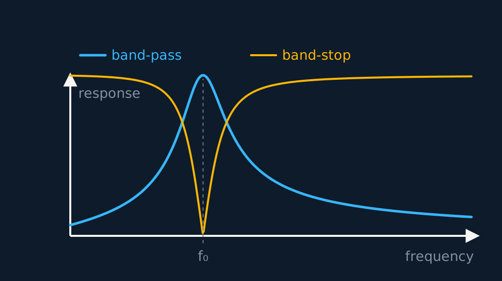
Both have uses. A receiver's band-pass keeps one station and rejects its neighbours. A band-stop removes a single unwanted frequency, such as 50 Hz mains hum on an audio line or an interfering transmitter close to the wanted frequency.
No tuned circuit passes a single frequency, and one that came close would be useless, because a real signal occupies a band of frequencies rather than a single line. The passband has to be wide enough to carry that band: if Q is too high, the higher audio frequencies of a broadcast are attenuated.
GUIDED PRACTICE
How fussy must a radio be
Medium-wave stations sit 9 kHz apart. A receiver tuned to 909 kHz has to keep its own station and reject the next one along. Estimate the Q its tuned circuit needs.
Show the working
The bandwidth it can afford is about the channel spacing, 9 kHz.
Q = = 909/9 = about 100, an ordinary figure for a coil and capacitor.
Check a designed bandwidth against the channel spacing rather than making it as narrow as the components allow. Sharper than 9 kHz here would start cutting into the station's own sidebands.
Filters without an inductor
Most filtering is done with a resistor and a capacitor and nothing else. Wire the pair in series across the signal and take the output from one of them. Across the capacitor, whose reactance is large at low frequency and small at high, low frequencies survive and high ones are shorted away, giving a low-pass filter. Across the resistor the two roles swap, and the same components become a high-pass filter.
Neither has a sharp edge. The response slides away over a decade or more, so the agreed marker of where a filter starts to act is the cut-off frequency, the frequency at which the reactance equals the resistance and the output has fallen to , about 0.71, of its full value. Setting equal to R gives it:
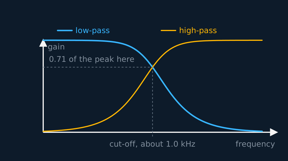
For the drawn pair = 1/(2π × 1600 × 0.10 × 10−6) = 995 Hz, about a kilohertz. Speech below that passes the low-pass version almost untouched, while a 10 kHz hiss, ten times the cut-off, comes out at a tenth of its size.
INDEPENDENT PRACTICE
Killing the hum
Speech from 300 Hz upward shares a line with 50 Hz mains hum. Choose the filter, and with R = 10 kΩ find the capacitor that puts the cut-off at 150 Hz. Estimate how much of the hum survives.
Show the working
A high-pass filter, since the wanted signal lies above the interference.
C = 1/(2πR) = 1/(2π × 150 × 10 × 103) = 1.1 × 10⁻⁷ F, about 0.11 μF.
At 50 Hz the frequency is a third of the cut-off, and the high-pass response there is 0.32, so about a third of the hum gets through. Speech at 300 Hz and above passes at 0.89 or better, so the wanted signal is barely touched.
ASSESSMENT FOCUS
- Name the output terminals in a filter answer. Output across the capacitor is low-pass, across the resistor is high-pass, and the cut-off is where the output has dropped to 0.71 of full size.
- The tuned circuit is read the same way. Across the resistor is band-pass, across the inductor and capacitor together is band-stop, and a response sketched without saying where it was measured has not answered the question.
- Convert before dividing in . Kilohms with microfarads give the product in seconds directly, so 1.6 kΩ with 0.10 μF is 1.6 × 10⁻⁴ s and a cut-off just under a kilohertz.
- A cut-off is not a wall. Say that the response falls away gradually and that the output at the cut-off itself is still 0.71 of full size, then estimate what survives; an answer that stops the signal dead at has described a filter nobody can build.
CHECK YOURSELF
An audio line carries speech from 300 Hz upwards together with 50 Hz mains hum. A filter is to be built from a 15 kΩ resistor and one capacitor, with its cut-off at 150 Hz. (a) State which kind of filter is needed and which component the output is taken across. (b) Calculate the capacitance. (c) State the output at the cut-off frequency itself, as a fraction of the full output.
Show a hint
Which side of the cut-off does the wanted signal lie on?
Show the answer
(a) The speech lies above the hum, so the filter must keep the high frequencies: a high-pass filter, with the output taken across the resistor.
(b) C = 1/(2πR) = 1/(2π × 150 × 15 × 103) = 7.1 × 10⁻⁸ F, about 71 nF.
(c) At the cut-off the reactance equals the resistance, so the output is , about 0.71, of the full output.
The 150 Hz cut-off is chosen to sit between the two, not on either. Putting it at 50 Hz would leave the hum at 0.71 of full size, and putting it at 300 Hz would attenuate the lowest speech the line is meant to carry.
Where the output is taken decides what the filter does.
A cut-off is where the output has fallen to 0.71 of full size, not where the signal stops.
Or read them with their mark schemes on the tuned circuits and the q factor questions page.
CHECK YOUR PROGRESS
Rate how confident you feel with each objective for this lesson. Ratings are saved in this browser, on this device, unless you sign in.
- Tell band-pass from band-stop and high-pass from low-pass, and find an RC filter's cut-off.
- Say why no filter passes a single frequency, and set a passband against the width of the signal it has to carry.
Open the full revision checklist to track your progress across the whole unit.