Physics › Electronics › Tuned circuits and the Q factor
Tuned circuits and the Q factor
At resonance an inductor's reactance and a capacitor's reactance are equal and cancel, which puts a tuned circuit's peak at f₀ = 1/2π√(LC). Series resonance is a current maximum, parallel resonance a supply-current minimum. The Q factor is f₀ over the half-power bandwidth, and resistance lowers it.
Choose your exam board to show the notes and questions relevant to your specification. You can change this setting at any time, and content for other boards remains available.
Resonant circuits and filters, part 1 of 2. Part 2 is Band-pass, band-stop and RC filters.
Builds on Capacitors and energy stored and Forced vibrations and resonance.
IN THIS TOPIC
- Find the resonant frequency of an LC circuit, and say what cancels at it.
- Tell the series circuit from the parallel one, say which quantity peaks in each, and use the mass on a spring as the analogy for both.
- Use Q and the half-power bandwidth together, and predict what extra resistance does to a resonance curve.
COMMON MISCONCEPTION
A tuned circuit responds at one frequency and rejects everything else.
It passes a band, not a line. The response falls to of the peak a half bandwidth either side of f0, and , so a real signal with its own spread of frequencies needs the band wide enough to carry it.
Where the reactances cancel
At resonance, the inductive and capacitive reactances have equal magnitudes. A series LCR circuit then has minimum impedance and maximum current; a parallel resonant circuit has maximum impedance and minimum supply current. The resonant frequency is , and . Increasing resistance reduces Q and broadens the response but does not change the ideal resonant frequency.
An inductor opposes a changing current, and it opposes it harder the faster the current changes, so its reactance rises with frequency. A capacitor does the opposite. It passes a rapidly alternating current easily and blocks a slow one, so its reactance falls as the frequency rises. Put the two in series and somewhere between the extremes their reactances are equal in size. They also act in opposite senses, so at that frequency they cancel and leave only the circuit's resistance to limit the current.
There the current from a given driving voltage is at its largest, and the circuit is at resonance. Setting the two reactances equal and solving for the frequency gives the point where it happens:
Both L and C sit under a square root, so a factor of four in either shifts the resonant frequency by a factor of two. Tuning exploits that gentleness. A variable capacitor swinging over a range of nine to one covers a frequency range of three to one, which is enough for a whole broadcast band on one knob.
WORKED EXAMPLE
Checking the marked peak
The circuit drawn above has L = 1.0 mH and C = 100 nF. Verify the resonant frequency marked on the graph.
= 1.0 × 10−3 × 100 × 10−9 = 1.0 × 10⁻¹⁰, and the square root of that is 1.0 × 10⁻⁵ s.
= 1/(2π × 1.0 × 10−5) = 1.59 × 10⁴ Hz = 15.9 kHz.
Take the root before dividing, and convert the prefixes before either. Millihenries or nanofarads left unconverted give an answer wrong by a power of ten.
Sharpness, and what resistance costs
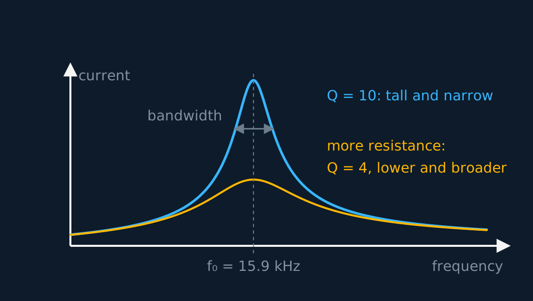
The two curves in that figure have the same L and C with different resistance, and together they define the Q factor. Measure the peak's width between the two frequencies at which the current has fallen to of its peak value. Power goes as the square of the current, so at those two frequencies the power delivered has dropped to half its peak, and they are known as the half-power points. The width between them is the bandwidth , written where a symbol for a width is wanted, and Q compares it against the resonant frequency itself:
In that second notation the same statement reads . A high quality factor Q corresponds to a narrow resonance peak. Resistance dissipates energy during each cycle, reducing Q. For a series circuit Q works out as . The cyan curve has 10 Ω and a Q of 10; raise the resistance to 25 Ω and Q drops to 4.
In bandwidth those two are 1.6 kHz and 4.0 kHz about the same 15.9 kHz centre. The peak did not move sideways, since depends on L and C alone. It fell, and it spread.
Side by side instead of end to end
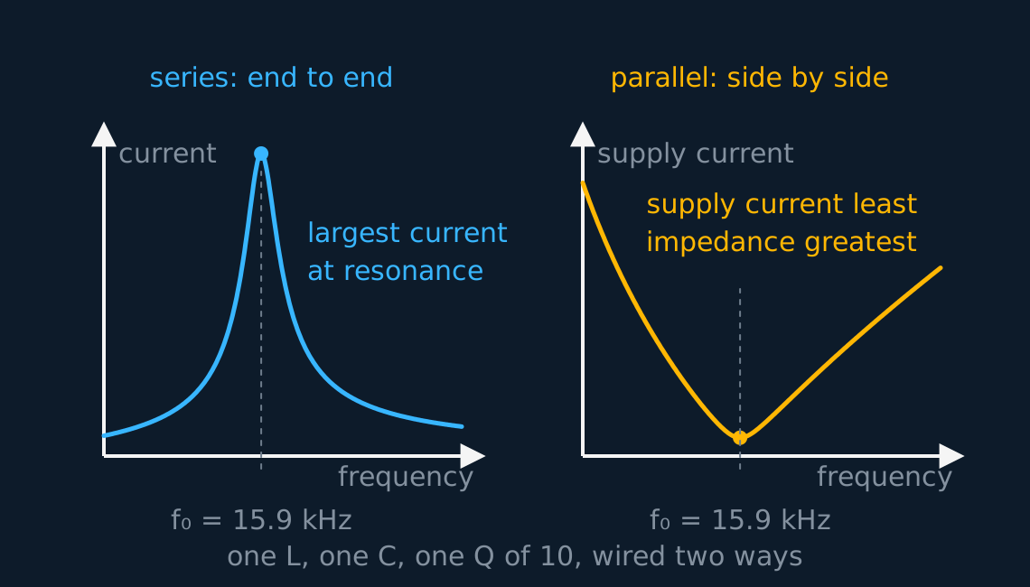
Put the inductor and the capacitor in parallel rather than in series and the behaviour reverses. Both branches now share the same pd, so each carries a current of its own, and those two currents are in antiphase: the capacitor's leads the applied voltage by a quarter of a cycle and the inductor's lags it by a quarter. At the frequency where the two reactances are equal in size the two branch currents are equal in size as well, so they cancel where the branches meet and the current drawn from the supply falls to a minimum. The pair presents its largest impedance at resonance, which is why the parallel circuit is called a rejector and the series one an acceptor.
Describe the drawing
Two panels on the same frequency scale for the same 1.0 millihenry and 100 nanofarad at a Q of 10. On the left the series current, as a fraction of its peak, rises to a maximum at 15.9 kilohertz; on the right the supply current drawn by the parallel pair, in multiples of its smallest value, falls to a minimum at that same 15.9 kilohertz, where the pair's impedance is greatest.
The branch currents themselves do not vanish. Charge continues to circulate around the loop formed by the capacitor and the inductor, and that circulating current is Q times the current drawn from the supply, because the supply replaces only the energy the loop's resistance dissipates each cycle. That factor of Q is a ratio of two impedances: at resonance the pair as a whole presents Q times the reactance of either branch on its own, so for the same applied pd the branch current is Q times the supply current.
Feed such a circuit through a series resistance, or from a transistor's drain, and the pd across it peaks sharply at resonance, since that is where its impedance is greatest. The resonant frequency is the same as before, so none of the tuning arithmetic changes. What changes is which quantity peaks: the current in the series circuit, the voltage in the parallel one.
Both circuits are analogous to a mass on a spring. Inductance plays the part of the mass, since it opposes a change of current exactly as inertia opposes a change of velocity. The capacitor is the spring, storing energy when it is charged as the spring stores it when it is stretched, and resistance is the damping. Energy shuttles between the magnetic and electric stores, each peaking twice per cycle, just as it shuttles between kinetic and potential in the oscillator, and the driving voltage plays the part of the hand that pushes the mass. A high Q is a lightly damped spring: a tall narrow response, and a long ring after the drive is removed.
WORKED EXAMPLE
A tank circuit for the medium wave
A parallel tuned circuit uses L = 250 μH with C = 400 pF, and its Q factor is 80. Find the resonant frequency and the half-power bandwidth, then find the current circulating in the loop when the supply delivers 1.2 mA.
= 250 × 10−6 × 400 × 10−12 = 1.0 × 10⁻¹³, whose square root is 3.16 × 10⁻⁷ s.
= 1/(2π × 3.16 × 10−7) = 503 kHz, in the middle of the medium-wave band.
= 503/80 = 6.3 kHz, so the response stays above half power from about 500 kHz to 506 kHz. Medium-wave stations sit 9 kHz apart, so a 6.3 kHz bandwidth rejects the neighbouring channels, but it is narrower than the channel being received, and the highest audio frequencies of the station fall outside it. A Q of 80 is therefore slightly too high here.
The circulating current is Q times the current from the supply, 80 × 1.2 = 96 mA. The supply current is small while the circulating current is large, so the coil has to be wound for 96 mA rather than for 1.2 mA.
Two filters from one tuned circuit has moved to the next part of this lesson.
Filters without an inductor has moved to the next part of this lesson.
ASSESSMENT FOCUS
- Convert the prefixes, multiply, then take the square root. Millihenries or nanofarads left unconverted give an wrong by a power of ten.
- Q and bandwidth travel together. , and the passband runs half a bandwidth either side of the resonant frequency, so quote a range when one is asked for. Its two edges are the half-power points, where the current has fallen to 0.71 of its peak.
- Series or parallel determines which quantity peaks. Series resonance is a current maximum at minimum impedance; parallel resonance is a supply-current minimum at maximum impedance, and what peaks there is the pd across the pair. Both share the same .
- Adding resistance never moves the resonant frequency. Say that first, then say the peak is lower and broader because Q has fallen.
CHECK YOURSELF
A tuned circuit uses L = 2.0 mH with C = 47 nF, and its Q factor is 25. Find the resonant frequency and the bandwidth, give the range of frequencies passed, and state what happens to each if resistance is added to the circuit. State also which quantity peaks at resonance if the same L and C are wired in parallel instead of in series.
Show a hint
Root LC first. Q compares the resonant frequency with the width of the peak.
Show the answer
= 2.0 × 10−3 × 47 × 10−9 = 9.4 × 10⁻¹¹, whose square root is 9.70 × 10⁻⁶ s.
= 1/(2π × 9.70 × 10−6) = 16.4 kHz.
= 16.4/25 = 0.66 kHz, so the circuit passes roughly 16.1 kHz to 16.7 kHz.
Extra resistance leaves exactly where it is, since that depends on L and C only. It lowers Q, so the peak falls and the bandwidth widens.
In parallel the two branch currents cancel at resonance, so the impedance is a maximum and the current drawn from the supply a minimum. What peaks is the pd across the pair, at the same 16.4 kHz.
At resonance the two reactances cancel, and f0 depends on L and C alone.
Series resonance peaks the current, parallel resonance peaks the voltage, and both are a mass on a spring with L for the mass and C for the spring.
Q is the resonant frequency over the half-power bandwidth, so added resistance lowers Q, broadens the peak and admits more of the neighbouring frequencies.
WORKBOOK
Printable practice for this topic: original exam-style questions with room to work, and a fully worked answer book. Free to use; please do not redistribute or sell.
Or read them with their mark schemes on the tuned circuits and the Q factor questions page.
CHECK YOUR PROGRESS
Rate how confident you feel with each objective for this lesson. Ratings are saved in this browser, on this device, unless you sign in.
- Find the resonant frequency of an LC circuit, and say what cancels at it.
- Tell the series circuit from the parallel one, say which quantity peaks in each, and use the mass on a spring as the analogy for both.
- Use Q and the half-power bandwidth together, and predict what extra resistance does to a resonance curve.
Open the full revision checklist to track your progress across the whole unit.