Physics › Required practicals › Interference: double slit and diffraction grating
REQUIRED PRACTICAL 2Interference: double slit and diffraction grating
Measuring interference effects, both with Young's two-slit arrangement and with a diffraction grating.
Theory: Interference and Young's double slit · Diffraction gratings
What you are trying to do
Measure the wavelength of laser light twice over: from the fringe spacing of a double-slit pattern, and from the diffraction angles of a grating. Comparing the two values is a cross-check on both.
Apparatus
- A laser pen or lab laser (class 2), on a stand so it cannot wander
- A double-slit slide of known slit separation, and a diffraction grating of known lines per millimetre
- A plain screen or wall, several metres away
- Metre rule for the fringes; tape measure for the longer distances
- A darkened room
Variables
- Independent: the slit-to-screen distance D (double slit); the order number n (grating)
- Dependent: the fringe spacing w; the position of each diffracted spot
- Control: the light source and its wavelength, and the slide in use: same slit separation or grating throughout
Method
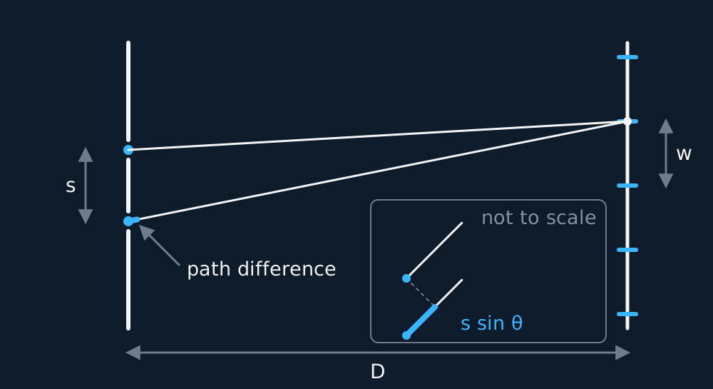
- Part one, the double slit. Mount the laser so its beam passes through both slits and falls on the screen a measured distance D away; start with D at least one and a half metres, and darken the room until the fringes are crisp.
Describe the drawing
Two slits a distance s apart, a screen a distance D away, and rays from both slits to the first bright fringe. The extra length the lower ray travels is the path difference between the two complete routes, marked in cyan where it leaves the slit; at the true angle it is only a few pixels long, so the same construction is repeated in the panel beside it at an angle chosen to be readable, where a perpendicular dropped from one slit onto the other slit's ray cuts off exactly that extra piece, s sin theta. The fringe spacing on the screen is w.
- Do not measure a single fringe. Mark the centres of eleven adjacent bright fringes with a pencil, so that ten spacings lie between the outer two, measure across all ten with a millimetre rule, and divide by ten. Keep the rule's resolution and the uncertainty of your measurement apart: the rule's resolution is 1 mm and no technique improves it, but the ±1 mm you carry on the whole span is spread over ten fringes instead of one, and dividing by an exact ten passes that percentage straight through to w.
- Repeat the measurement at several different values of D, moving the screen back in steps of half a metre.
- Part two, the grating. Replace the slide with the grating, set it square to the beam, and let the pattern of sharp spots fall on the wall a measured distance L away.
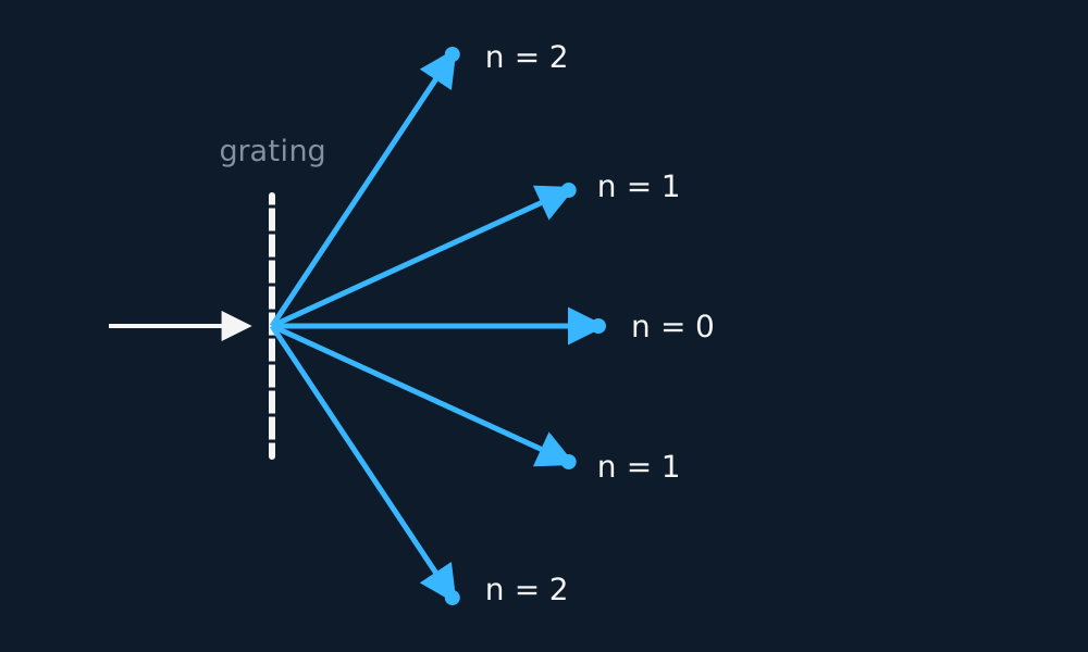
- For each order n, measure the distance from the central spot to the nth spot on both sides, and average the pair: any small misalignment of the grating then cancels.
Analysis
- Double slit: plot w against D and fit a straight line without constraining it. The model w = λD/s predicts a line through the origin with gradient λ/s, so the wavelength is the gradient multiplied by the slit separation; a significant intercept indicates a systematic error in D or in the fringe measurement rather than a different wavelength.
- Grating: for each order, θ comes from tan θ = x/L, and the wavelength from λ = d sin θ/n. Use sin of the measured angle, never x/L itself: the grating angles are far too large for the small-angle shortcut.
- Compare the two wavelengths, each quoted with its own uncertainty.
- What the agreement supports. The methods use different optical elements and equations, so agreement within combined uncertainty is a useful cross-check. They may still share systematic effects, including distance calibration, alignment and laser wavelength. Neither method establishes the wavelength of anything but this laser.
- The ceiling on the double-slit answer. The wavelength comes out as a gradient multiplied by the slit separation, and that separation arrives on a printed label. Whatever tolerance the manufacturer allowed passes straight into your answer, and no amount of care with the fringes shrinks it. That is the practical limit of the double slit here, and it is why the grating usually gives the more precise value: hundreds of lines per millimetre are ruled far more precisely, the maxima are sharp instead of broad, and the angles are large enough to measure rather than infer.
Worked readings: the double slit
A 650 nm laser through slits 0.40 mm apart, fringes measured ten spacings at a time:
| D / m | Ten spacings / mm | w / mm |
|---|---|---|
| 1.50 | 24.4 | 2.44 |
| 2.00 | 32.5 | 3.25 |
| 2.50 | 40.6 | 4.06 |
| 3.00 | 48.8 | 4.88 |
| 3.50 | 56.9 | 5.69 |
Idealised illustrative data, chosen so the working is easy to follow. Real readings scatter about the line rather than sitting on it, and your own graph will have points either side of the best fit.
Each w is a ten-spacing measurement divided by ten. Plotting w against D gives a straight line, with no intercept in these idealised readings, of gradient (5.69 − 2.44) mm/(3.50 − 1.50) m = 1.625 mm per metre. Then λ = gradient × s = 1.625 × 10⁻³ × 4.00 × 10⁻⁴ = 6.50 × 10⁻⁷ m, which is 650 nm.
Worked readings: the grating
The same laser through a 300 lines-per-millimetre grating, spots measured on a wall:
| Order n | x / m | θ / ° | λ / nm |
|---|---|---|---|
| 1 | 0.398 | 11.2 | 650 |
| 2 | 0.847 | 23.0 | 650 |
| 3 | 1.443 | 35.8 | 650 |
Idealised illustrative data, chosen so the working is easy to follow. Real readings scatter about the line rather than sitting on it, and your own graph will have points either side of the best fit.
With 300 lines per millimetre the slit spacing is d = 1/300 mm = 3.33 × 10⁻⁶ m, and the wall is L = 2.00 m away. For each order, θ comes from tan θ = x/L and the wavelength from d sin θ/n; all three orders return 650 nm, agreeing with the double-slit value. As a final check, n ≤ d/λ = 5.13, so only 5 orders can exist each side, however big the screen.
Evaluating the result
Idealised double-slit readings with one of them miscounted. Ten fringe spacings need eleven pencil marks, and at 2.50 m there were only 10: nine spacings were measured and the total was still divided by ten. The third column divides w by D, which is λ/s and the same at every screen distance.
| D / m | w / mm | w/D / mm m⁻¹ |
|---|---|---|
| 1.50 | 2.44 | 1.625 |
| 2.00 | 3.25 | 1.625 |
| 2.50 | 3.66 | 1.463 |
| 3.00 | 4.88 | 1.625 |
Idealised illustrative data, chosen so the working is easy to follow. Real readings scatter about the line rather than sitting on it, and your own graph will have points either side of the best fit.
Three rows give 1.625 mm m⁻¹ and the miscounted one gives 1.463, low by exactly a tenth. The error is a fixed fraction rather than a random slip, because dividing by ten a span that covers nine spacings scales every fringe spacing by 9/10. A miscount does not always make w too small: counting the marks instead of the gaps makes it too small, while dividing by fewer spacings than were measured makes it too large, so establish which count was taken rather than assume a direction. On the w against D graph the point sits below an otherwise straight line. Count the pencil marks again, and measure that screen distance a second time. Keep the original reading in the table with the reason recorded, even if the repeat replaces it in the fit.
Where the uncertainty comes from
- Fringe spacing: Three separate numbers, and running them together gives the wrong uncertainty. The rule's resolution is 1 mm, a property of the instrument. The span across ten spacings is read at two ends, half a division at each, so it carries about ±1 mm. At D = 1.50 m that is ±1 mm in 24.4 mm, or 4.1%. The fringe spacing w is that span divided by an exact ten, so its absolute uncertainty is ±0.1 mm and its percentage uncertainty is the span's, 4.1%. Measure a single fringe instead and the same ±1 mm lands on 2.44 mm, which is 41%. That factor of ten is the reason for counting ten.
- Slit separation: Taken from the manufacturer's label, so its uncertainty is fixed before you start; it usually dominates the double-slit result.
- Distances D and L: Metres long and measured with a tape, so their percentage uncertainty is small; longer is better on both counts.
- Grating angles: Higher orders sit at larger angles, where the same centimetre of position error moves sin θ less: quote the higher orders with more confidence, and average both sides.
What earns the marks
✓Marks
- Say you measured across ten fringe spacings and divided, and say why: it cuts the percentage uncertainty in w tenfold.
- Give the reason for a large D: wider fringes, easier to measure, at the cost of dimmer ones, so the room is darkened.
- For the grating, state that you measured to the same order on both sides and averaged, and that θ came from tan θ = x/L before taking sin θ.
- Know why the grating gives the more precise value: many slits make the maxima sharp, and the angles are large enough to measure well.
- The order count is capped because sin θ cannot exceed 1: show n ≤ d/λ and round down to the highest order that can exist.
Safety
!Caution
Use a school-approved Class 2 visible laser: its safety case assumes the natural blink and aversion response limits an accidental exposure to a fraction of a second, so never stare into the beam or its specular reflections. Remove shiny objects from the beam line, keep the beam below or above eye level, terminate it on a matte screen, and follow the local risk assessment.
Method and analysis here follow the standard approach; your school may vary the apparatus. Always follow your teacher’s risk assessment in the lab.