Physics › Electricity › Sensing circuits and the potentiometer
Sensing circuits and the potentiometer
Put a thermistor or a light dependent resistor in one arm of a divider and the output pd follows temperature or illumination. Which resistor carries the output sets whether it rises or falls. A potentiometer balanced to a galvanometer null draws no current, so it reads an emf and not a terminal pd.
Choose your exam board to show the notes and questions relevant to your specification. You can change this setting at any time, and content for other boards remains available.
Watch Sensing circuits and the potentiometer on the InkPhysics YouTube channel
Potential dividers, part 2 of 2. Part 1 is The potential divider and its output.
Builds on The potential divider and its output.
IN THIS TOPIC
- Design sensing dividers from thermistors and LDRs, choosing which resistor carries the output.
- For CIE, compare potential differences on a potentiometer, and say what the galvanometer does in a null method.
COMMON MISCONCEPTION
Warming the thermistor always raises the output voltage.
Which way the output moves depends on where the output is taken. Warming an ntc thermistor lowers its resistance and its share of the supply, so an output taken across the fixed resistor rises and an output taken across the thermistor falls.
Sensing circuits
Replace one resistor with a component whose resistance depends on temperature or on illumination and the divider becomes a sensor. An ntc thermistor's resistance falls as it warms; a light dependent resistor (LDR) behaves the same way towards light, its resistance falling as the illumination rises. Either way, the changing resistance changes the ratio of the two resistances, so the output pd changes with the quantity being sensed.
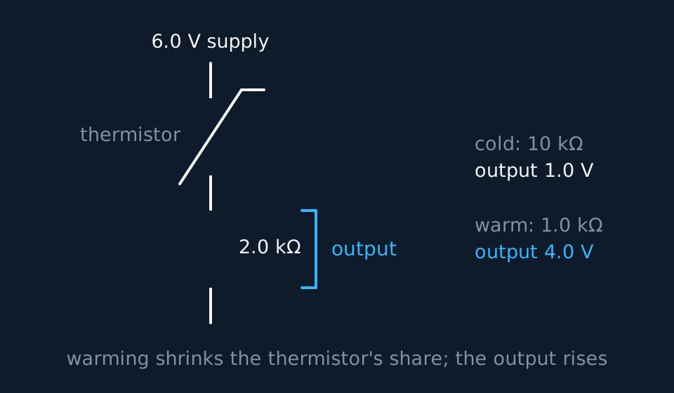
The design decision is which resistor the output is taken across. With the output across the fixed resistor, warming the thermistor raises the output, which is the direction needed to switch on a fan. With the output across the thermistor, warming lowers the output, which is the direction needed to switch on a heater. The position of the output in the divider therefore sets the direction of the change.
GUIDED PRACTICE
An LDR sensing divider
An LDR (100 kΩ in darkness, 1.0 kΩ in daylight) sits above a fixed 10 kΩ resistor across a 6.0 V supply, output across the fixed resistor. Find the output voltage in the dark and in the light.
Show the working
In the dark, Vout = 6.0 × 10/(100 + 10) = 0.55 V. In daylight, 6.0 × 10/(1.0 + 10) = 5.5 V.
The output changes by a factor of ten between darkness and daylight, which is enough to operate a switching circuit. The divider has converted a resistance change into a change in output pd.
The potentiometer and null methods, a CIE extension
CIE requires the potentiometer as a means of comparing potential differences, and the role of a galvanometer in a null method; this section applies to CIE candidates. OCR includes the potentiometer only as the three-terminal potential divider with a sliding contact covered in the previous lesson, and Edexcel requires the uniform wire on which it is built. The null method itself is required by CIE alone.
The arrangement is that same metre of uniform resistance wire, now laid along a scale, with a driving cell across its ends keeping a steady current in it. The potential falls uniformly along it, so the pd between one end and any point is proportional to the length of wire between them. Tapping the wire at 65.0 cm of a 100.0 cm run driven at 2.00 V gives 1.30 V, and the wire has become a divider with a scale printed alongside it. The sliding contact in the previous lesson supplied a variable pd; here the pd across the tapped length is the quantity another source is balanced against.
Now the measurement. Connect the cell you want to measure between that same end of the wire and a sliding contact, the jockey, with a galvanometer in the branch, and connect it so that its emf opposes the pd along the wire. Slide the jockey until the galvanometer reads exactly zero. That is the balance point, and at balance the two pds are equal and opposite, so the cell's emf equals the pd across the tapped length.
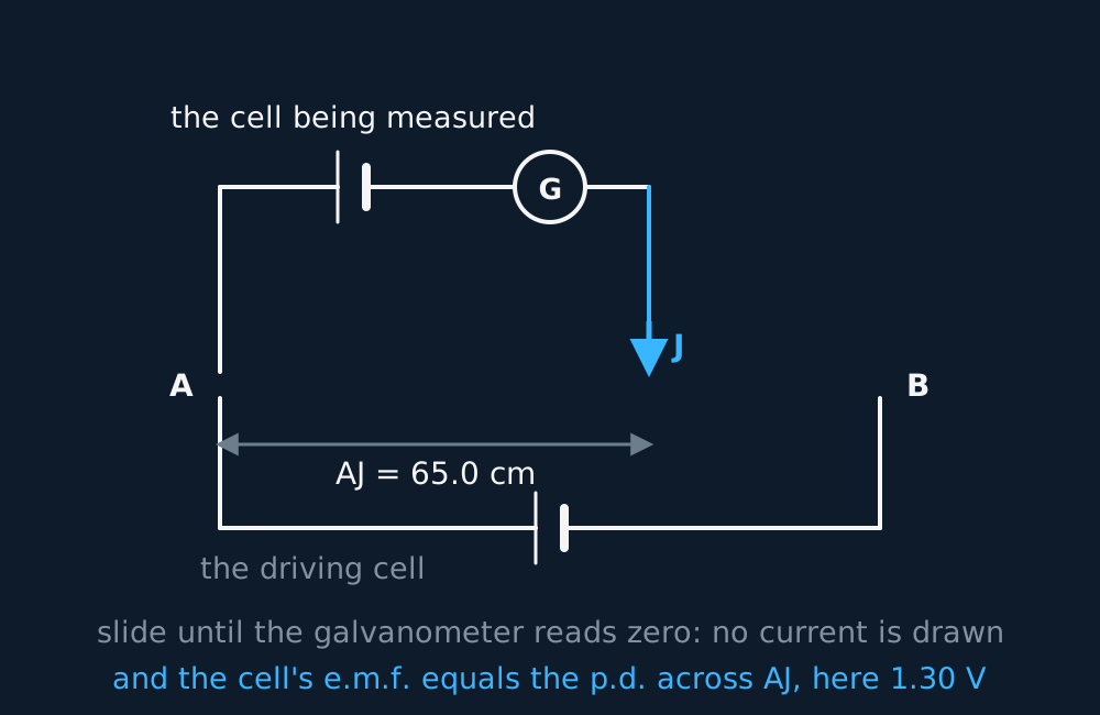
At the balance point no current flows in the branch, so the cell being measured drops no lost volts inside itself and you read its emf rather than its terminal pd. Nor does the branch load the wire, so the divider ratio is the plain length ratio. A voltmeter cannot do either of those things perfectly, because a real voltmeter has finite input resistance and so draws some current, tiny for a modern digital meter, larger for a moving-coil needle.
Comparing two potential differences is then a matter of two balance lengths. Balance one source at l1, swap it for the other, rebalance at l2, and divide.
The properties of the driving circuit cancel from the ratio, so no value for the driving emf or the wire's resistance is needed. Both balances must be taken with the driving circuit undisturbed: a driving cell that runs down between the two readings changes the potential gradient and invalidates the comparison.
The galvanometer is sensitive and centre-zero, and needs no calibration. No value is read from it, only a zero, so an error in its scale does not affect the result. That is what a null method means: the instrument locates a balance rather than measuring a quantity.
Its own resistance does not shift the position of the balance point either, since at balance it carries no current. It does set how sharply the balance can be located, because it determines the current driven by a given imbalance, so a higher-resistance detector gives a broader, less definite null.
The direction of the deflection indicates which way to move the jockey. A deflection in the same direction at both ends of the wire indicates that the pd across the whole wire is smaller than the emf being measured, or that the cell is connected the wrong way round.
Circuit-symbol conventions vary slightly between exam boards. Use the symbol set supplied with your specification and identify the galvanometer by its role as a null detector.
WORKED EXAMPLE
Comparing two cells
On a 100.0 cm potentiometer wire, a standard cell of emf 1.018 V balances at 50.9 cm. An unknown cell, measured with the same driving circuit, balances at 32.5 cm. Find its emf.
The wire is uniform, so the pd tapped off is proportional to the balance length, and the two emfs sit in the ratio of the two lengths.
E2 = 1.018 × 32.5/50.9 = 0.650 V.
The driving emf, the current in the wire and the resistance of any component do not appear in the calculation. Two balance lengths and one known emf are sufficient, which is why the potentiometer was the standard laboratory method for measuring an emf before digital meters.
ASSESSMENT FOCUS
- State the change in share as well as the change in resistance. Warming a thermistor lowers its resistance, so its share of the supply pd falls and the other resistor's share rises, and an output taken across that other resistor rises.
- State the LDR's behaviour in words: its resistance falls as light intensity rises. That statement carries credit in its own right.
- For “design a circuit that…”, name the component, its position in the divider, and which resistor the output is taken across. All three are required.
- CIE only: at the balance point of a potentiometer no current flows in the branch, so the reading is an emf and not a terminal pd. State that, then use the ratio of balance lengths for the calculation.
CHECK YOURSELF
A thermistor sits above a fixed 8.0 kΩ resistor across a 12 V supply, with the output taken across the fixed resistor. (a) The thermistor warms up. What happens to the output, and why? (b) What single change would make the output fall as the thermistor warms instead?
Show a hint
Neither part needs a number. Consider the change in the resistance ratio, then the position of the output.
Show the answer
(a) Warming an ntc thermistor lowers its resistance, so its share of the 12 V falls and the share across the fixed 8.0 kΩ resistor, the output, rises towards 12 V. The supply pd is unchanged; the resistance ratio has changed.
(b) Take the output across the thermistor instead. Its falling share is then the output, so warming makes the output fall. The position of the output sets the direction of the change.
Changing one resistance changes how the supply pd is shared.
At balance no current flows in the branch, so a potentiometer reads an emf and not a terminal pd.
Or read them with their mark schemes on the potential divider and its output questions page.
CHECK YOUR PROGRESS
Rate how confident you feel with each objective for this lesson. Ratings are saved in this browser, on this device, unless you sign in.
- Design sensing dividers from thermistors and LDRs, choosing which resistor carries the output.
- For CIE, compare potential differences on a potentiometer, and say what the galvanometer does in a null method.
Open the full revision checklist to track your progress across the whole unit.