Physics › Electronics › Flip-flops, counters and clocks
Flip-flops, counters and clocks
A D-type flip-flop copies its data input to its output on each rising clock edge and holds it between edges, storing one bit. Wire a row of them to toggle and every stage halves the frequency, so the chain counts in binary. An astable supplies the clock that steps it.
Choose your exam board to show the notes and questions relevant to your specification. You can change this setting at any time, and content for other boards remains available.
Digital signal processing, part 2 of 2. Part 1 is Combinational logic.
Builds on Combinational logic and The ideal op-amp and the comparator.
IN THIS TOPIC
- Describe the D-type flip-flop as a one-bit memory, and use counters that halve the frequency at every stage.
- Reset a chain early to count modulo n, and tell BCD, up/down and Johnson counters apart.
- Read the pulse width, frequency, mark-to-space ratio and duty cycle off an astable's output.
COMMON MISCONCEPTION
An astable's duty cycle is its high time divided by its low time.
That ratio, t₁/t₂, is the mark-to-space ratio. The duty cycle is the high time as a fraction of the whole period, t₁/(t₁ + t₂), quoted as a percentage: a 3:1 mark-to-space is a 75% duty cycle, not 300%.
Memory, and counting by halving
Gates have no memory; release a switch and the output reverts immediately. Sequential circuits add the missing ingredient with the D-type flip-flop, a one-bit memory. It has a data input D, a clock input, and an output Q. On each rising clock edge it copies whatever is on D to Q, then holds Q frozen until the next edge, ignoring D completely in between. Registers and other small fast storage are rows of these, one per bit; bulk memory uses denser cells instead, a capacitor per bit in DRAM and charge-trapping transistors in flash.
One connection turns that one-bit memory into a frequency divider. Connect the flip-flop's inverted output back to its own D input and every clock edge loads the opposite of what Q held, so Q toggles at each edge. Two clock cycles pass before Q completes one full cycle of its own, so Q runs at half the clock frequency, a clean square wave. Feed that stage's inverted output onward as the clock of a second stage and the halving repeats. For n stages,
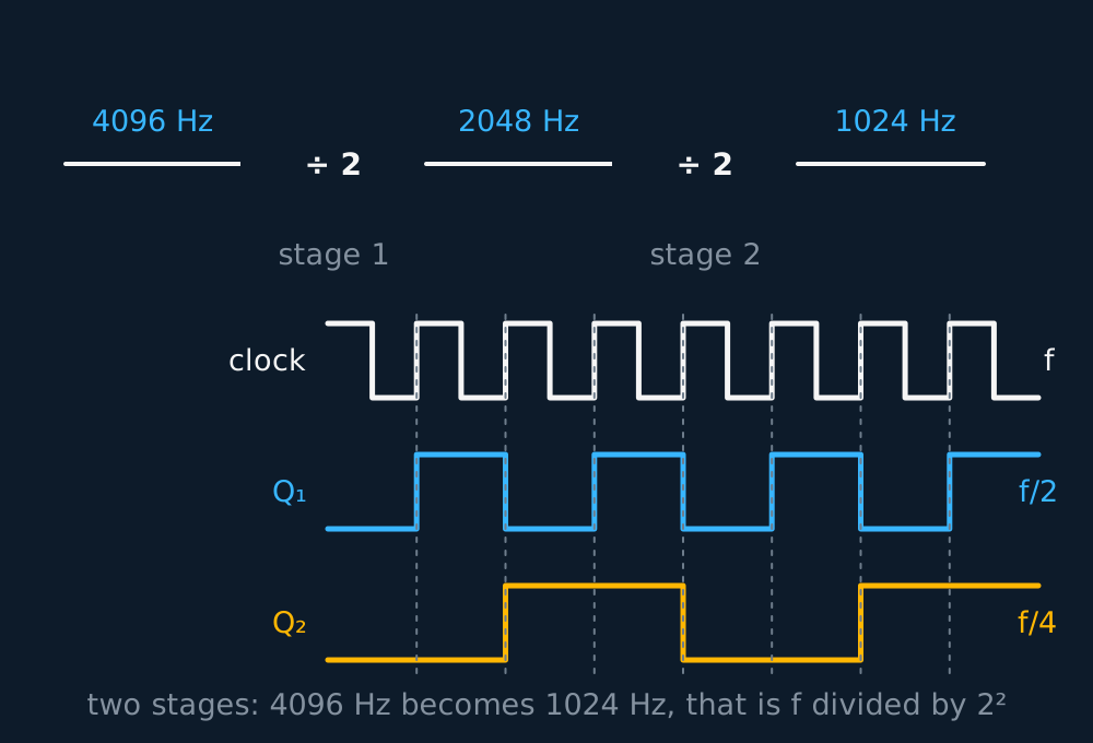
Read all the Q outputs at once, last stage first, and the same chain is a binary counter. The outputs step through 00, 01, 10, 11 and onward, one count per clock pulse, rolling over after states. Counting and frequency division are the same circuit described two ways.
WORKED EXAMPLE
The watch that counts out one second
A quartz watch crystal oscillates at 32 768 Hz. How many toggling stages does the watch need to derive its once-per-second tick?
32 768 is , so each of 15 halvings takes the frequency down one power of two, ending at exactly 1 Hz.
That number is designed backwards. Crystal makers chose 32 768 Hz precisely because a whole number of halvings lands on one second.
INDEPENDENT PRACTICE
Designing the divider
A timing circuit is clocked at 4096 Hz and must drive a display at 16 Hz. How many flip-flop stages are needed, and how many distinct states does that chain pass through as a counter?
Show the working
The division needed is 4096/16 = 256 = , so 8 stages.
An 8-stage counter runs through = 256 states, 0 to 255, before repeating.
Keep the two answers apart. Frequency out is ; the number of states counted is .
Counters that stop where you want them to
A plain chain always runs to and rolls over, and that is rarely the number anybody wants. Wire the outputs that are high at the unwanted count into a NAND gate, and take its output to the reset input of every stage. The instant that count appears the gate clears the whole chain, so the count never persists there and the chain starts again from zero instead. Detect ten, 1010, and the chain counts 0000 up to 1001 and resets: a modulo-10, or decade, counter. Any modulus is available by choosing which outputs feed the gate.
The decade is the useful one, because a decimal digit has exactly ten states. Four bits holding 0000 to 1001 and nothing above is binary-coded decimal, and a BCD counter is a decade counter read as one decimal digit. Cascade them, the last output of each decade clocking the next, and the units decade rolls over once per ten pulses while the tens decade rolls over once per hundred, so four of them drive a display reading 0 to 9999 with no arithmetic in between. A frequency meter is that row of BCD counters behind a gate that lets pulses through for exactly one second.
Counting backwards needs one extra connection per stage. Each flip-flop copies D on a rising edge, so a stage clocked from the previous stage's inverted output steps the count up, and the same stage clocked from Q instead steps it down. An up/down counter brings both routes to a pair of gates in every stage and lets a single direction input choose between them, which is what a lift controller requires when it has to track how many floors are left in either direction.
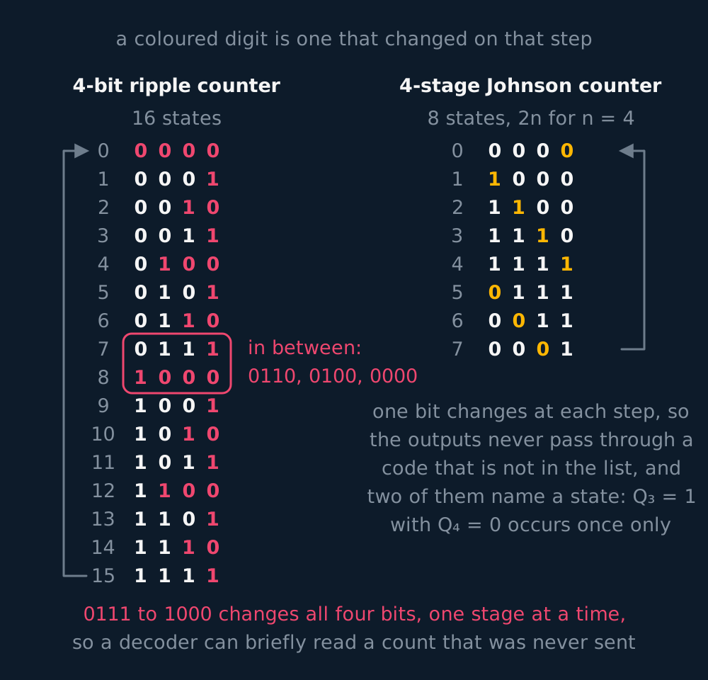
A Johnson counter gives up the ripple altogether. Put n flip-flops in a row, all clocked together, each output feeding the next one's D input so that a pattern shifts one place along the row per pulse, and then bring the last stage's inverted output back to the first stage's D. From 0000 the row fills with ones from the left, 1000, 1100, 1110, 1111, and the inverted feedback then fills it with zeros the same way, 0111, 0011, 0001, 0000. Four stages therefore cycle through eight states rather than sixteen, and n stages through 2n.
Using only half the available states has two consequences. Only one output changes at each step, so the outputs never pass through a wrong combination on their way to the right one as a ripple chain does, and any single state can be recognised by a two-input gate rather than an n-input one. Where a ripple counter is asked only for a number, a Johnson counter is asked for clean, glitch-free timing signals in a fixed order.
GUIDED PRACTICE
Choosing the chain
A circuit must count from 0 to 11 and repeat. How many flip-flops does it need, and which count must the reset gate detect? Then state how many states a 5-stage Johnson counter passes through.
Show the working
Twelve states need at least twelve, and = 8 is too few, so 4 flip-flops, which offer sixteen.
The chain must be cleared as soon as it reaches twelve, so the gate detects 1100, watching the 8s and 4s outputs. The counter then shows 0000 to 1011, which is 0 to 11.
A Johnson counter gives 2n states, so five stages give 10 states, not = 32.
Count the states rather than the top number. A modulo-12 counter reaches 11, so the count the reset gate detects is one more than the highest count displayed.
The astable, which supplies the clock
Every counter above waits on a clock, and something has to make one. A comparator will, once it is given a memory of its own. Feed a fraction of the output back to the non-inverting input, which is positive feedback, and the circuit holds whichever rail it has reached until the other input is dragged past the threshold that fraction sets. Now charge a capacitor towards the output through a resistor and take the inverting input from it. The capacitor climbs, crosses the upper threshold, and the output flips; it then falls towards the other rail, crosses the lower threshold, and the output flips back. Neither state is stable, so it never stops. That is an astable.
All the timing lives in the charging. Each interval lasts a fixed multiple of the RC of whichever path is charging the capacitor during it, the multiple set by where the thresholds sit, so doubling that resistance doubles that interval and touches nothing else. Give the two directions separate paths, a pair of resistors each with a diode that lets current through one way only, and the high time and the low time become independent of each other.
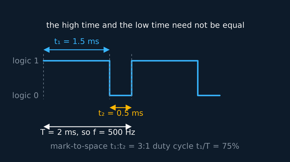
Three numbers describe the output, and questions ask for them by name. The pulse width is the length of the high part on its own, . The period is and the frequency is its reciprocal. The mark-to-space ratio is the high time divided by the low time, , quoted as a ratio. The duty cycle is the high time as a fraction of the whole period, , quoted as a percentage. Equal intervals give a square wave, mark-to-space 1:1 at a duty cycle of 50%.
WORKED EXAMPLE
Reading an astable's output
An astable's output is high for 1.5 ms and low for 0.50 ms. Give the pulse width, the frequency, the mark-to-space ratio and the duty cycle. The resistance in the path that sets the low time is then doubled: give the new duty cycle and frequency.
The pulse width is the high time alone, 1.5 ms. The period is 1.5 + 0.50 = 2.0 ms, so f = 1/(2.0 × 10−3) = 500 Hz.
Mark-to-space = 1.5/0.50 = 3.0, written 3:1. Duty cycle = 1.5/2.0 = 0.75, or 75%.
Doubling that resistance doubles the low time to 1.0 ms, so the period becomes 2.5 ms. Duty cycle = 1.5/2.5 = 60% and f = 1/(2.5 × 10−3) = 400 Hz.
Changing one interval changes the frequency as well as the ratio. Only altering both paths together keeps the frequency where it was.
A counter responds to any of those settings, since it acts on an edge, provided the pulse stays wide enough and its edges sharp enough to meet the counter's own timing requirements; make a pulse too narrow or too slow-edged and even an edge-triggered input misses it.
For a load switched by a MOSFET the duty cycle is what matters. The duty cycle is the fraction of the time the channel is open, so it fixes the average power the load receives: modelling the lamp as a constant resistance, one fed at 20% duty from a 12 V supply is being given a fifth of the power it would take at 100% (a real filament's resistance shifts with temperature, so the proportion belongs to the model), while the switch itself stays cool because it is either fully on or fully off.
ASSESSMENT FOCUS
- The D-type in one line: on the clock's rising edge it copies D to Q, and holds Q between edges. The qualitative description is what is required.
- Counter arithmetic: frequency divides by , the number of states is . Decide which the question wants before reaching for the calculator.
- A modulo-n counter is a chain plus a gate that spots n and resets it, so it displays 0 to n − 1. A decade counter is the modulo-10 case and one BCD digit. A Johnson counter of n stages has 2n states, not .
- Astable numbers are three separate quantities. Pulse width is the high time by itself, mark-to-space is high over low, duty cycle is high over the period as a percentage. Write which one you are giving.
CHECK YOURSELF
A 4-stage binary counter is clocked at 96 Hz. Find the frequency at its final output, and state how many distinct states it passes through. The chain is then wired to reset the instant it reaches 1010: state the counter this makes and the range of counts it now shows. The astable supplying the 96 Hz clock is high for 3.0 ms and low for 7.4 ms: give its pulse width, mark-to-space ratio and duty cycle.
Show a hint
Each stage halves the frequency, and a chain of n stages has 2 to the n states. A reset gate firing at ten leaves the counts below it. Keep the astable's three numbers apart.
Show the answer
Four halvings divide by = 16, so the final output runs at 96/16 = 6 Hz.
A free-running 4-stage chain passes through = 16 states, 0000 up to 1111, before rolling over.
Resetting the instant 1010 (ten) appears makes a modulo-10, or decade, counter: it now shows 0000 up to 1001, that is 0 to 9, then returns to zero.
The pulse width is the high time alone, 3.0 ms, and the mark-to-space ratio is 3.0/7.4 = 0.41, about 1:2.5.
The period is 3.0 + 7.4 = 10.4 ms, which matches the 96 Hz clock, so the duty cycle is 3.0/10.4 = 29%.
A D-type flip-flop copies its input to its output on each rising clock edge and holds it between edges, so it stores one bit.
Every toggling stage halves the frequency, so n stages divide by 2 to the n, and a gate that resets the chain early counts modulo n.
An astable's mark-to-space ratio is its high time over its low time; its duty cycle is its high time over the whole period.
Or read them with their mark schemes on the combinational logic questions page.
CHECK YOUR PROGRESS
Rate how confident you feel with each objective for this lesson. Ratings are saved in this browser, on this device, unless you sign in.
- Describe the D-type flip-flop as a one-bit memory, and use counters that halve the frequency at every stage.
- Reset a chain early to count modulo n, and tell BCD, up/down and Johnson counters apart.
- Read the pulse width, frequency, mark-to-space ratio and duty cycle off an astable's output.
Open the full revision checklist to track your progress across the whole unit.