Physics › Electronics › Negative feedback amplifiers
Negative feedback amplifiers
Negative feedback returns part of the output to the inverting input, trading gain for bandwidth and a closed-loop gain set by two resistors. The inverting amplifier gives −Rf/Rin about a virtual earth and the non-inverting gives 1 + Rf/R1, and the gain-bandwidth product fixes what each costs.
Choose your exam board to show the notes and questions relevant to your specification. You can change this setting at any time, and content for other boards remains available.
Operational amplifiers, part 2 of 2. Part 1 is The ideal op-amp and the comparator.
Builds on The ideal op-amp and the comparator and Potential dividers.
IN THIS TOPIC
- Say what negative feedback sacrifices and what it gains.
- Use the inverting gain, and explain the virtual earth that produces it.
- Use the non-inverting gain, and use the gain-bandwidth product to find a bandwidth.
COMMON MISCONCEPTION
Negative feedback throws gain away and gets nothing back.
Negative feedback spends surplus gain and buys something for it: the closed-loop gain is set by two resistors rather than the chip, and the bandwidth grows as the gain falls, gain × bandwidth staying constant. Less gain, but gain you can rely on.
Giving the gain away on purpose
With no feedback, any workable input difference sends the output straight to a supply rail, so an open-loop op-amp can only compare. To amplify, the open-loop gain has to be reduced, and it is reduced using the output's own voltage.
Feed a fraction of the output back to the inverting input and the circuit becomes self-correcting. If the output rises too far, the fed-back share raises , which reduces the input difference and brings the output back down. The output settles where the two inputs are almost equal, and with an open-loop gain of about 105 that means within microvolts.
The closed-loop gain then depends on the feedback network rather than on the chip. Surrendering most of the available gain gives a gain set by chosen resistors, a wider bandwidth, less distortion, and behaviour that is largely independent of the individual op-amp.
The inverting amplifier and its virtual earth
The inverting amplifier earths the non-inverting input and feeds the signal through to the inverting input, with bridging that input to the output. Feedback holds the two inputs within microvolts of each other, and one of them is at 0 V, so the other is held at 0 V as well without being connected to earth at all. That node is the virtual earth.
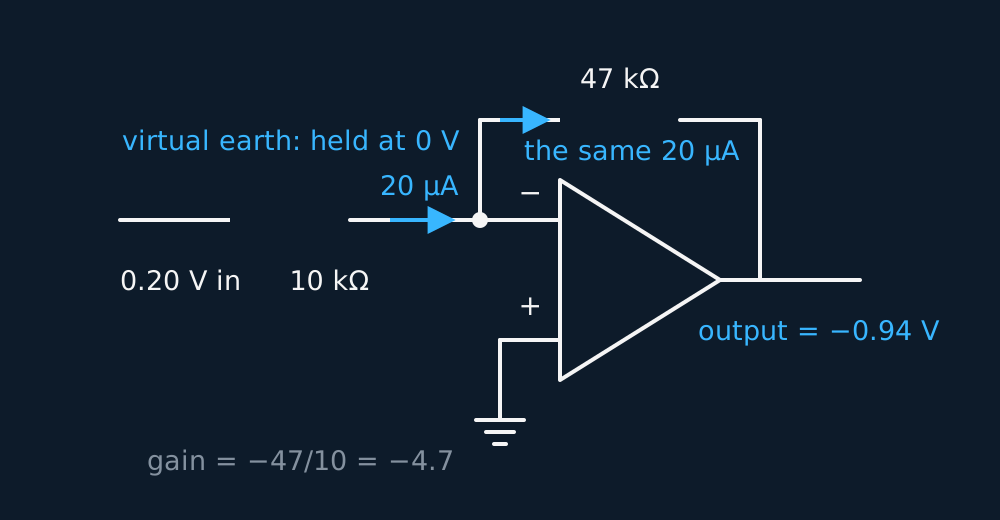
Two facts finish the derivation. The current arriving through is , since one end of that resistor is at and the other is at 0 V. None of it enters the op-amp, so all of it runs on through , and the output must sit at minus that current times . Divide one by the other and the chip has vanished from the answer:
WORKED EXAMPLE
Following the current round
In the figure = 0.20 V, = 10 kΩ and = 47 kΩ. Find the current into the virtual earth and the output voltage, then check against the gain equation.
The input resistor has the whole 0.20 V across it, so I = 0.20/(10 × 103) = 20 μA.
That current continues through the 47 kΩ resistor from a node at 0 V, so the output is −20 × 10−6 × 47 × 103 = −0.94 V.
The gain equation agrees, −(47/10) × 0.20 = −0.94 V. Learn the current route anyway, because the derivation marks are written for it.
The non-inverting amplifier
Move the signal to the non-inverting input and return the feedback through a divider of and hung across the output. The divider offers the inverting input the fraction of whatever the output is doing, and feedback drives the output until that fraction matches . Rearranging gives a gain of
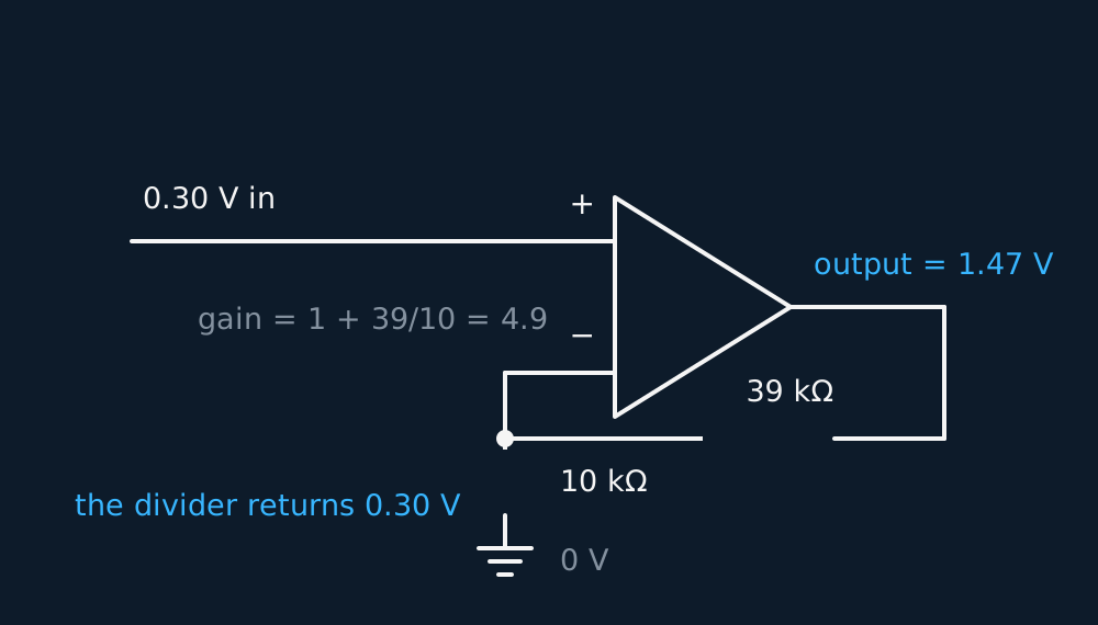
Two differences from the inverting circuit matter in an exam. The output is in phase with the input, and the gain can never fall below one, since the 1 is stuck at the front. The signal also arrives straight at the op-amp's own input terminal, so the circuit draws almost nothing from whatever drives it. A high-resistance sensor is far better read this way.
GUIDED PRACTICE
Designing to a number
An instrument needs a non-inverting amplifier of gain 11, built with 1.0 kΩ as . Find , and state the gain the same two resistors would give in the inverting arrangement.
Show the working
1 + /1.0 = 11, so = 10 kΩ.
In the inverting circuit the same pair gives −10/1.0 = −10.
The non-inverting gain is always one greater in magnitude, and the output keeps the phase of the input. Quoting alone for a non-inverting design gives a gain one too small.
What the bargain costs: gain-bandwidth product
The bandwidth a real op-amp has is small. For the same representative compensated device, the open-loop gain of 105 only holds up to about 10 Hz, and above that the gain falls in proportion to frequency until it reaches one at around 1 MHz. Multiply the gain by the frequency at which it runs out and the answer is the same everywhere along that slope:
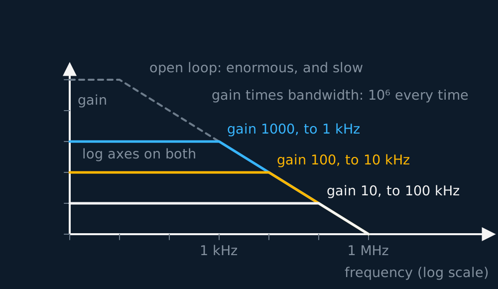
The trade in negative feedback is therefore a quantitative one. Ask a 1 MHz chip for a closed-loop gain of 1000 and its corner lands at 1 kHz; settle for a gain of 10 and the same chip corners at 100 kHz. Every factor of ten of gain surrendered gives a factor of ten of bandwidth.
Be careful with the word flat. The corner quoted as a bandwidth is where the gain has already fallen to , about 0.71, of its low-frequency value, the same 0.71 that fixed a filter's cut-off earlier in this unit, which is why it is called the 3 dB point. A bandwidth of 1 kHz therefore means flat to within that 0.71 up to 1 kHz, not untouched up to it. Cascade two identical stages and each contributes its own 0.71 at the shared corner, leaving the pair at 0.71 × 0.71 = 0.50 there, so a chain is always narrower than any one of its stages.
INDEPENDENT PRACTICE
Enough bandwidth for audio
An op-amp has a gain-bandwidth product of 1.0 MHz, and an audio stage must reach 20 kHz. Find the gain that puts one stage's corner at 20 kHz. Two such stages are then cascaded: give the overall gain, and say where the pair has fallen to 0.71. Then find the gain per stage that would put the pair's own 0.71 point at 20 kHz.
Show the working
Gain = 1.0 × 10⁶/(20 × 103) = 50, so one stage of gain 50 has already dropped to 0.71 of its flat value at 20 kHz.
Two of them give an overall gain of 50 × 50 = 2500, but each is at 0.71 there, so the pair is at 0.71 × 0.71 = 0.50 of flat at 20 kHz, not flat at all. The pair reaches 0.71 far earlier, where , that is at 0.644 of the stage corner: 20 × 0.644 = 12.9 kHz.
For the pair to hold 0.71 out to 20 kHz each stage needs its corner at 20/0.644 = 31.1 kHz, so a gain of 1.0 × 10⁶/(31.1 × 103) = 32. Two stages of 32 give 1024 overall and reach 0.71 at 20.1 kHz.
Splitting a large gain between stages still gains bandwidth, since one stage of gain 1024 would corner at 1.0 × 10⁶/1024 = 977 Hz. Test the bandwidth tolerance on the whole chain rather than on one stage.
ASSESSMENT FOCUS
- The virtual earth carries the derivation marks. The inverting input is held at 0 V, the input current is , no current enters the op-amp, so all of it flows on through .
- Mind the signs. Inverting gain is negative and the output is in antiphase; non-inverting gain is positive and can never drop below 1.
- Hold every calculated output against the supply rails before writing it down. If it exceeds them, say the amplifier saturates and give the output as the rail voltage.
- Bandwidth questions are one division. Gain-bandwidth product over the closed-loop gain, and the two always move in opposite directions. That answer is the frequency at which the gain has fallen to 0.71, so a cascade of stages reaches 0.71 sooner than any single stage in it.
CHECK YOURSELF
An op-amp with an open-loop gain of 1.0 × 10⁵, a gain-bandwidth product of 1.0 MHz and an output that saturates at ±13 V is wired as an inverting amplifier with = 5.0 kΩ and = 100 kΩ. Find the closed-loop gain and the bandwidth, then the output for an input of 0.10 V and for an input of 1.0 V.
Show a hint
Gain from the resistor ratio, bandwidth from the product, and hold each answer against the rails.
Show the answer
Gain = − = −100/5.0 = −20, so the output is inverted and twenty times larger.
Bandwidth = 1.0 × 10⁶/20 = 50 kHz.
For 0.10 V in, the output is −20 × 0.10 = −2.0 V, comfortably inside the rails.
For 1.0 V in, the equation asks for −20 V. The output cannot pass the rail, so the amplifier saturates at about −13 V and the waveform is clipped flat.
Negative feedback makes the closed-loop gain depend primarily on the resistor ratio. For an approximately fixed gain-bandwidth product, reducing gain increases bandwidth.
Inverting gain is minus Rf over Rin about a virtual earth; non-inverting gain is 1 + Rf over R1.
Or read them with their mark schemes on the ideal op-amp and the comparator questions page.
WHERE TO GO NEXT
- Rearranging equations is the maths this lesson leans on, worked through from GCSE.
CHECK YOUR PROGRESS
Rate how confident you feel with each objective for this lesson. Ratings are saved in this browser, on this device, unless you sign in.
- Say what negative feedback sacrifices and what it gains.
- Use the inverting gain, and explain the virtual earth that produces it.
- Use the non-inverting gain, and use the gain-bandwidth product to find a bandwidth.
Open the full revision checklist to track your progress across the whole unit.