Physics › Electronics › Summing and difference amplifiers
Summing and difference amplifiers
A summing amplifier hangs several input resistors on one virtual earth, so its output is minus the sum of the inputs, each weighted by Rf over its own input resistor. Weights in powers of two make a digital-to-analogue converter. Rearranged, the same op-amp subtracts, cancelling interference common to both inputs.

Choose your exam board to show the notes and questions relevant to your specification. You can change this setting at any time, and content for other boards remains available.
Builds on Negative feedback amplifiers and Circuit symbols and Kirchhoff's laws.
IN THIS TOPIC
- Use the summing amplifier equation, choosing a separate gain for each input through its own resistor.
- Explain how weighted resistors turn a binary number into an analogue voltage.
- Use the difference amplifier equation, and explain how it removes interference shared by both inputs.
- Spot when saturation or resistor tolerance makes the ideal equations fail.
COMMON MISCONCEPTION
A summing amplifier simply adds up its input voltages.
It adds weighted voltages, and inverts the total. Each input reaches the virtual earth through its own resistor, so it arrives with its own gain Rf/Rin: equal weights happen only if you choose equal resistors.
Every input meets a virtual earth
In an inverting amplifier, one input resistor feeds the op-amp's inverting input, and negative feedback holds that input within microvolts of 0 V. That node is the virtual earth. Because the node sits at 0 V, the current arriving through an input resistor is just the input voltage over that resistance, and because the op-amp inputs draw no appreciable current, every bit of that current must leave through the feedback resistor.
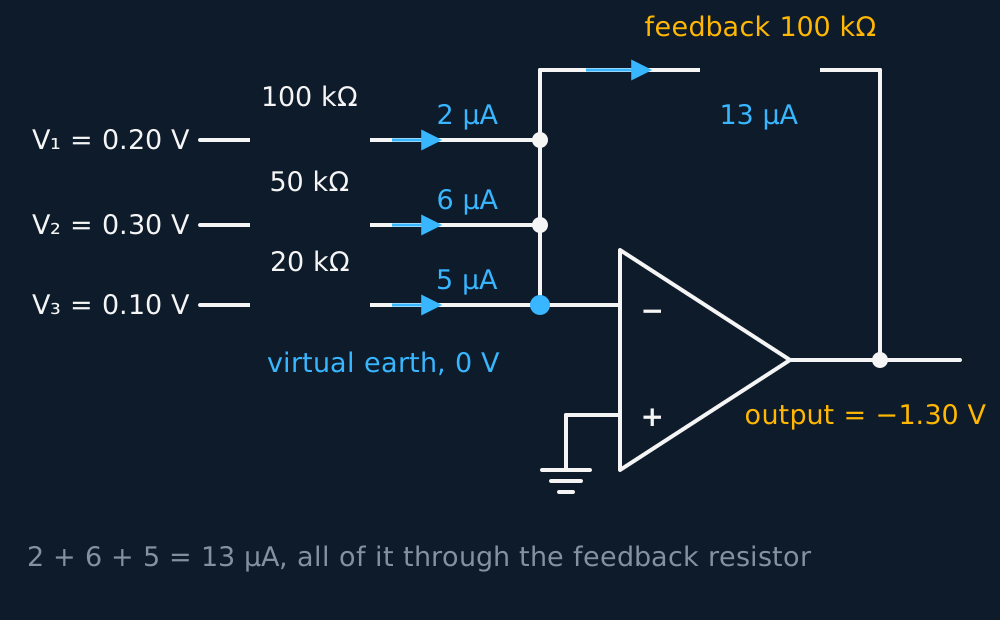
Now hang several input resistors on the same node, one per signal. Each input drives its own current into the virtual earth without disturbing the others, the currents add at the node, and the whole total is forced through . The output swings to whatever voltage makes that happen, so it carries an inverted, weighted copy of every input at once:
Describe the drawing
Three input resistors of one hundred, fifty and twenty kilohms carry two, six and five microamps from their sources into one summing point held at zero volts by the op-amp. The thirteen microamp total leaves through the hundred kilohm feedback resistor, so the output sits at minus one point three volts.
Read the equation as a set of independent gains. Input 1 is amplified by , input 2 by , and so on. The circuit does not add the voltages themselves; it adds weighted voltages and inverts the total, and the weights are set by the choice of resistors.
WORKED EXAMPLE
Two microphones, one wire
A mixer uses = 100 kΩ. A singer's microphone feeds = 100 kΩ and a quieter guitar feeds = 50 kΩ. At one instant = 0.20 V and = −0.15 V. Find the output.
The gains first: = 1 for the voice, = 2 for the guitar, boosting the weaker source.
= −(1 × 0.20 + 2 × (−0.15)) = −(0.20 − 0.30) = +0.10 V.
Note the double negative. The guitar's negative swing, amplified and inverted along with everything else, leaves the output positive. Track the sign of each input separately before summing.
Weighted resistors: from binary to analogue
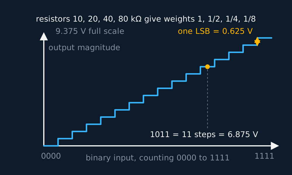
Choose the weights in powers of two and the mixer becomes a digital-to-analogue converter, a DAC. A 4-bit binary number arrives as four logic levels, each 0 V or 5.0 V. Give the most significant bit the strongest channel and halve the gain at each step down, say = 10 kΩ with input resistors of 10, 20, 40 and 80 kΩ. The gains run 1, , , , matching the place values 8, 4, 2, 1.
One least significant bit is then worth 5.0 × 10/80 = 0.625 V of output. Feed in the binary count 0000, 0001, 0010 and upward, and the output descends an even staircase, one 0.625 V step per count, sixteen levels in all. Every digital audio player ends in some refinement of this idea.
Describe the drawing
A staircase of sixteen equal treads: the size of the analogue output of a four-bit weighted resistor converter as its input counts from 0000 to 1111. The inverting circuit makes the output itself negative, so the voltage descends as the count rises. Each tread is one least significant bit, nought point six two five volts, and the code 1011 lands eleven steps out at six point eight seven five volts.
GUIDED PRACTICE
The staircase, step by step
Using the DAC above, with logic 1 = 5.0 V, find the magnitude of the output for the input 1011, and check it against the step size.
Show the working
Only the bits at logic 1 contribute. MSB: 5.0 × 1 = 5.0 V. Third bit: 5.0 × = 1.25 V. LSB: 5.0 × = 0.625 V.
Total magnitude 5.0 + 1.25 + 0.625 = 6.875 V, at the output as −6.875 V.
Check the result against the count: 1011 is eleven, and 11 × 0.625 V = 6.875 V. A weighted sum that disagrees with count times step means one resistor weight is wrong.
The difference amplifier
Swap the geometry and the op-amp subtracts. A difference amplifier feeds one signal towards each input through matched resistor pairs, and its output amplifies only the gap between them:
Watch Difference amplifiers: how the noise cancels on the InkPhysics YouTube channel
Subtraction matters most for small sensor signals. A strain gauge or thermistor usually sits in a bridge, a pair of potential dividers across one supply. In balance both divider midpoints sit at the same voltage. When the sensor shifts, the two midpoints separate by millivolts, and that small difference is superimposed on a large steady level that carries no information. The difference amplifier rejects the shared level and amplifies the difference alone.
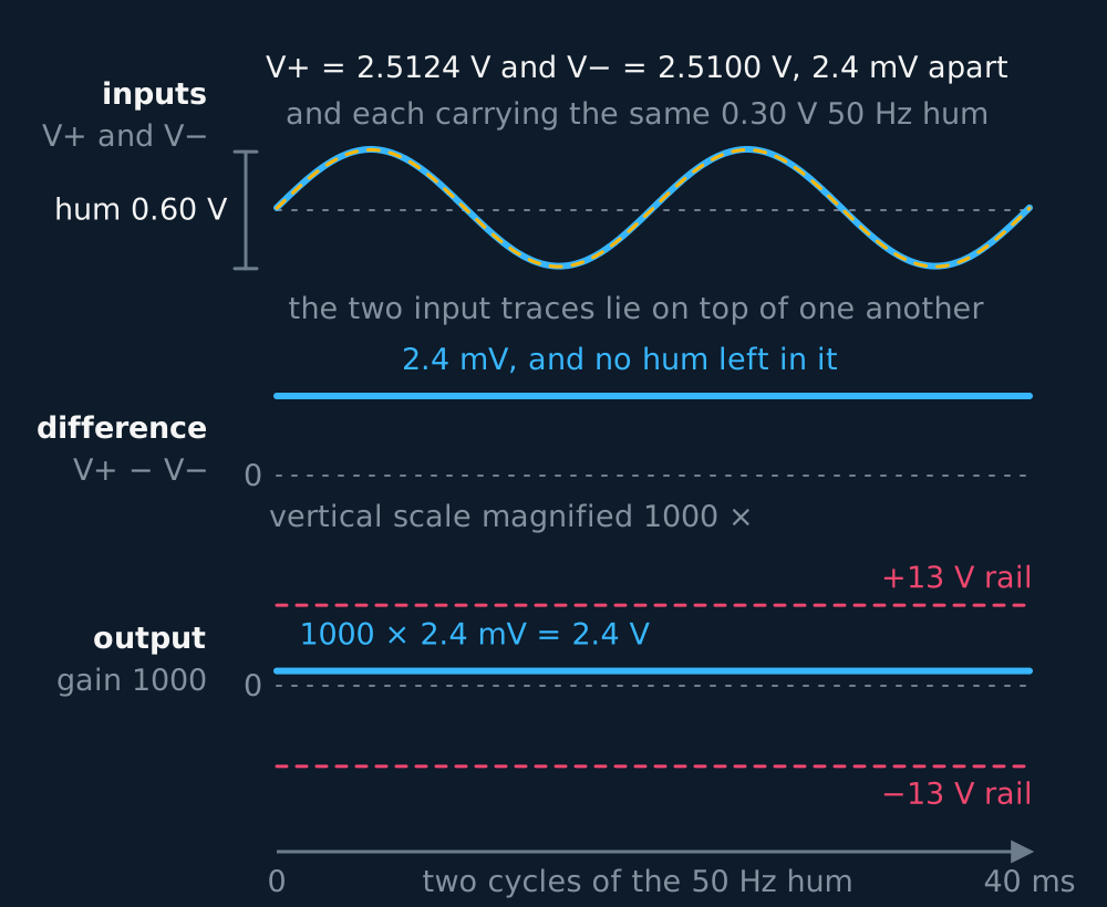
The same subtraction is the standard cure for interference. Mains wiring induces the same 50 Hz hum on both leads of a sensor cable, since the leads run side by side. Identical on both inputs, the hum is common-mode, and wipes it out before the gain is applied. The wanted signal, applied as a genuine difference between the leads, survives at full gain.
WORKED EXAMPLE
Reading a strain gauge through the hum
A bridge produces = 2.5124 V and = 2.5100 V, both carrying an identical 0.30 V mains hum. The difference amplifier has = 1000. Find the output.
= (2.5124 − 2.5100) × 1000 = 2.4 × 10−3 × 1000 = 2.4 V.
The 2.51 V standing level and the 0.30 V of hum appear in both terms of the subtraction, so neither reaches the output. Amplifying alone by 1000 would have demanded an absurd 2500 V and buried the signal in 300 V of amplified hum.
Describe the drawing
Three traces sharing one forty millisecond time axis. At the top the two bridge leads swing together through six tenths of a volt of mains hum, and because they sit only 2.4 mV apart they are drawn one on top of the other. In the middle their difference, on a scale magnified a thousand times, is a flat line at 2.4 mV with no ripple left in it at all, because the hum was identical on both leads and subtracts to nothing. At the foot the output, that difference at a gain of a thousand, is a steady 2.4 V lying well inside the dashed rails at plus and minus thirteen volts, which is where the ideal equation would stop.
Limits: saturation and resistor tolerance
The equations allow any output at all; the hardware does not. An op-amp runs from supply rails, typically ±15 V, and its output cannot pass them. Ask the summing equation for −20 V and the real output runs into saturation a volt or so inside the negative rail and sits there, clipping the waveform flat. Every design should end with the same check, worst-case output against the rails.
The other limit comes from the resistors. Every gain here is a ratio of real resistors, and real resistors come with a tolerance, commonly 5% or 1%. Two 5% resistors can leave a gain almost 10% adrift. A DAC feels this hardest, because its staircase is only trustworthy if each weight is accurate to under half a step. For an 8-bit converter that means resistor ratios good to about 0.2%, and needing eight precision values spanning a 128 to 1 range is exactly what drives real converters away from the weighted-resistor design.
INDEPENDENT PRACTICE
Pushed past the rails
A summing amplifier has gains of 2 and 4 on its two inputs and runs from ±15 V rails, saturating at ±13 V. Inputs are = 2.0 V and = 3.0 V. What does the output actually do? Keeping = 2.0 V, find the largest the amplifier can handle linearly.
Show the working
The ideal output is −(2 × 2.0 + 4 × 3.0) = −16 V. That lies beyond the −13 V limit, so the real output saturates at −13 V and the waveform is clipped.
For linear working the magnitude must stay within 13 V, so 4 + 4 ≤ 13, giving ≤ 2.25 V.
Compute the ideal output first, then compare it with the supply rails before quoting it.
ASSESSMENT FOCUS
- Work out each input's own gain before touching the voltages. Adding the voltages first and applying a single gain to the total weights every input equally, which gives the wrong output whenever the input resistors differ.
- The output is inverted. State the sign, then the size: a missing minus sign reverses the polarity of the output being described.
- Difference amplifier answers subtract first and multiply after. Quote the order: , then times .
- Common-mode rejection is a one-sentence explanation. Interference induced identically on both inputs appears in both terms of the subtraction, so it cancels, while the wanted signal is a genuine difference and is amplified.
- Whenever supplies are given, check the ideal output against the rails. If it exceeds them, say the amplifier saturates and give the output as (near) the rail voltage.
- Base the derivation on the virtual earth. Say the inverting input is held at 0 V, the input currents are , they add at the node, and all of the total flows through .
CHECK YOURSELF
A summing amplifier has = 120 kΩ, with = 1.5 V through = 60 kΩ and = −0.8 V through = 30 kΩ. The supplies are ±15 V and the op-amp saturates at ±13 V. Find the output, and then the output if falls to −5.0 V.
Show a hint
Each input has its own gain of Rf over its own resistor. Mind both signs, then mind the rails.
Show the answer
The gains are 120/60 = 2 and 120/30 = 4.
= −(2 × 1.5 + 4 × (−0.8)) = −(3.0 − 3.2) = +0.2 V. The channel with the larger gain sets the sign of the output.
With = −5.0 V the ideal output is −(3.0 − 20) = +17 V, beyond the +13 V limit, so the amplifier saturates at about +13 V and the output no longer follows the equation.
For a summing amplifier, each input contributes −(Rf/Rin)Vin to the output. The total output is the sum of these contributions, subject to the supply-rail limits.
The difference amplifier gives Rf over R1 times (V+ − V−), so interference shared by both inputs subtracts to nothing.
No output passes the supply rails; past them the amplifier saturates and clips.
WORKBOOK
Printable practice for this topic: original exam-style questions with room to work, and a fully worked answer book. Free to use; please do not redistribute or sell.
Or read them with their mark schemes on the summing and difference amplifiers questions page.
CHECK YOUR PROGRESS
Rate how confident you feel with each objective for this lesson. Ratings are saved in this browser, on this device, unless you sign in.
- Use the summing amplifier equation, choosing a separate gain for each input through its own resistor.
- Explain how weighted resistors turn a binary number into an analogue voltage.
- Use the difference amplifier equation, and explain how it removes interference shared by both inputs.
- Spot when saturation or resistor tolerance makes the ideal equations fail.
Open the full revision checklist to track your progress across the whole unit.