Physics › Engineering physics › Heat engines and their efficiency
Heat engines and their efficiency
A heat engine turns part of the heat from a hot source into work and must reject the rest, so the two kelvin temperatures cap its efficiency. Four strokes and two revolutions make one cycle, and the area the indicator loop encloses is the work per cycle. Input, indicated, brake and friction power show where the energy is lost.
Choose your exam board to show the notes and questions relevant to your specification. You can change this setting at any time, and content for other boards remains available.
Heat engines and heat pumps, part 1 of 2. Part 2 is Heat pumps and combined heat and power.
Builds on Non-flow processes and p-V diagrams and Angular momentum and rotational power.
IN THIS TOPIC
- Describe the engine cycle and calculate efficiency from W, Q_H and Q_C, and its theoretical ceiling from the kelvin temperatures.
- Explain why no heat engine can be 100% efficient, and why the ceiling rises with a hotter source or colder sink.
- Describe the four strokes of a petrol and a diesel engine, and map each onto its theoretical cycle.
- Read an indicator diagram, take the work per cycle from its area, and say how the real loop differs from the theoretical one.
- Audit a real engine with input, indicated, brake and friction power, and with thermal, mechanical and overall efficiency.
COMMON MISCONCEPTION
A perfect engine would turn all the fuel's heat into useful work.
Even a perfect engine must dump heat. The working substance has to be returned to its starting state each cycle, so heat QC is rejected to a colder sink and the efficiency is capped at (TH − TC)/TH, below 1 for any real pair of temperatures.
The engine cycle
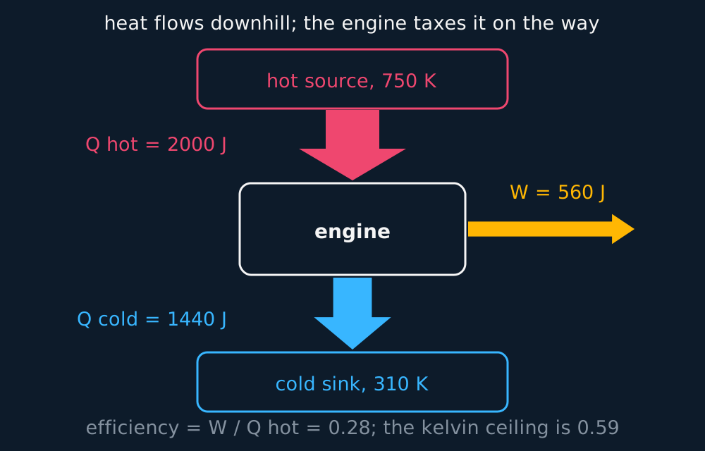
Every heat engine, whether petrol, diesel or steam turbine, is the same machine in outline. A working substance, usually a gas, is carried round a repeating cycle. Each cycle it absorbs heat QH from a hot source, converts part of that heat to work W, and must dump the remainder QC into a cold sink, the surroundings. Energy conservation fixes W = QH − QC, and the fraction of the input that became work is the efficiency:
Describe the drawing
An energy-flow diagram: a wide coral arrow of 2000 joules leaves the hot source at 750 kelvin and enters the engine, an amber arrow of 560 joules leaves sideways as work, and a coral-to-cyan arrow of the remaining 1440 joules is dumped into the cold sink at 310 kelvin. The arrow widths are proportional, so the 28 per cent efficiency can be read off the geometry.
A cyclic heat engine must reject some energy to a colder reservoir so that the working substance can return to its initial state. It cannot convert all supplied heat into work. In the idealised closed cycle the theory works with, resetting the gas means compressing it, which requires rejecting heat somewhere colder; a real open-flow engine expels its burnt charge and draws a fresh one, but the energy accounting comes out the same. The best possible cycle running between source temperature TH and sink temperature TC achieves
with both temperatures in kelvin. The formula is a ratio of absolute temperatures, so Celsius numbers wreck it; only the kelvin scale starts at the true zero the ratio needs. Real engines fall short of even this ceiling, through friction, turbulence and heat leaking where it should not.
WORKED EXAMPLE
A power station's ceiling
A turbine takes steam at 850 K and rejects heat to cooling towers at 300 K. Find its maximum theoretical efficiency, and comment on its measured efficiency of 40%.
Maximum efficiency = (TH − TC)/TH = (850 − 300)/850 = 0.65.
The real 40% sits well below the 65% ceiling, and the gap is friction, imperfect insulation and the compromises of running fast. Engineers chase the ceiling from both ends, hotter steam and colder cooling water, because both raise the theoretical limit itself.
Four strokes to one cycle
A piston engine runs that cycle in a cylinder, and it takes four strokes of the piston, two full turns of the crankshaft, to get round it once. The induction stroke fills the cylinder: the inlet valve opens and the piston travels down, drawing the charge in at roughly atmospheric pressure. The compression stroke shuts both valves and brings the piston back up, squeezing that charge into a small volume and heating it on the way. It happens quickly, so little heat escapes and the squeeze is close to adiabatic.
Then the power stroke, the only one that delivers work. The charge burns, the pressure jumps, and the hot gas drives the piston down, expanding and cooling while the crankshaft takes the work away. Last is the exhaust stroke: the exhaust valve opens, the pressure falls to atmospheric as the burnt gas escapes, and the rising piston pushes out what is left. The cylinder is back to its starting state, and one power stroke has arrived for every two revolutions.
Petrol and diesel engines differ in what gets compressed and in what lights it. A petrol engine draws in a mixture of air and fuel and compresses it by a factor of about ten, as far as it dare go before the mixture fires itself, and a spark plug ignites it at the top of the stroke. The burn is over before the piston has moved appreciably, so on the theoretical cycle the heat QH goes in at constant volume, drawn as a vertical climb in pressure at the smallest volume.
A diesel engine draws in air alone and compresses it far harder, by a factor of fifteen to twenty, which takes it to something like 900 K, far above the temperature at which the fuel ignites. Fuel is then sprayed in at the top of the stroke and burns as fast as it arrives, while the piston is already moving down, so on the theoretical cycle its heat goes in at constant pressure. No spark plug is needed, and the higher compression ratio is why a diesel's ceiling, and its measured efficiency, sit above a petrol engine's.
The two theoretical cycles agree on the rest. Expansion is adiabatic down to the largest volume; the exhaust valve opening is drawn as a fall in pressure at constant volume, and that fall is where QC leaves; and the induction and exhaust strokes run out and back along the bottom of the diagram at atmospheric pressure.
The indicator diagram
An indicator diagram is that loop measured rather than imagined, the pressure of the gas in one cylinder plotted against its volume while the engine actually runs. Reading it needs nothing new. Work is the area under a curve, rightward motion is expansion and does positive work, leftward motion is compression and costs it.
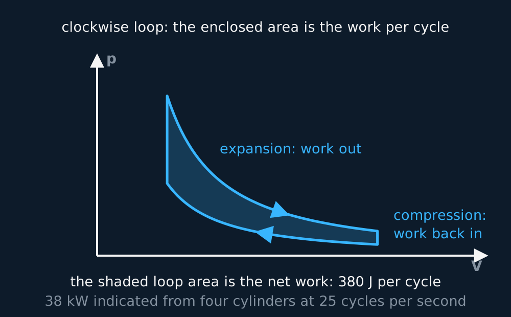
On the p-V diagram a full cycle is a closed loop, traversed clockwise for an engine. Expansion happens along the high-pressure top, compression along the low-pressure bottom, so the work out exceeds the work back in, and the difference, the net work per cycle, is the area enclosed by the loop.
Describe the drawing
A closed clockwise loop on a pressure-volume diagram, shaded inside: the gas expands along the high-pressure upper curve doing work, and is compressed back along the lower curve for less work returned. The difference, the enclosed area, is 380 joules of net work per cycle, which for four cylinders at 25 cycles a second is 38 kilowatts of indicated power.
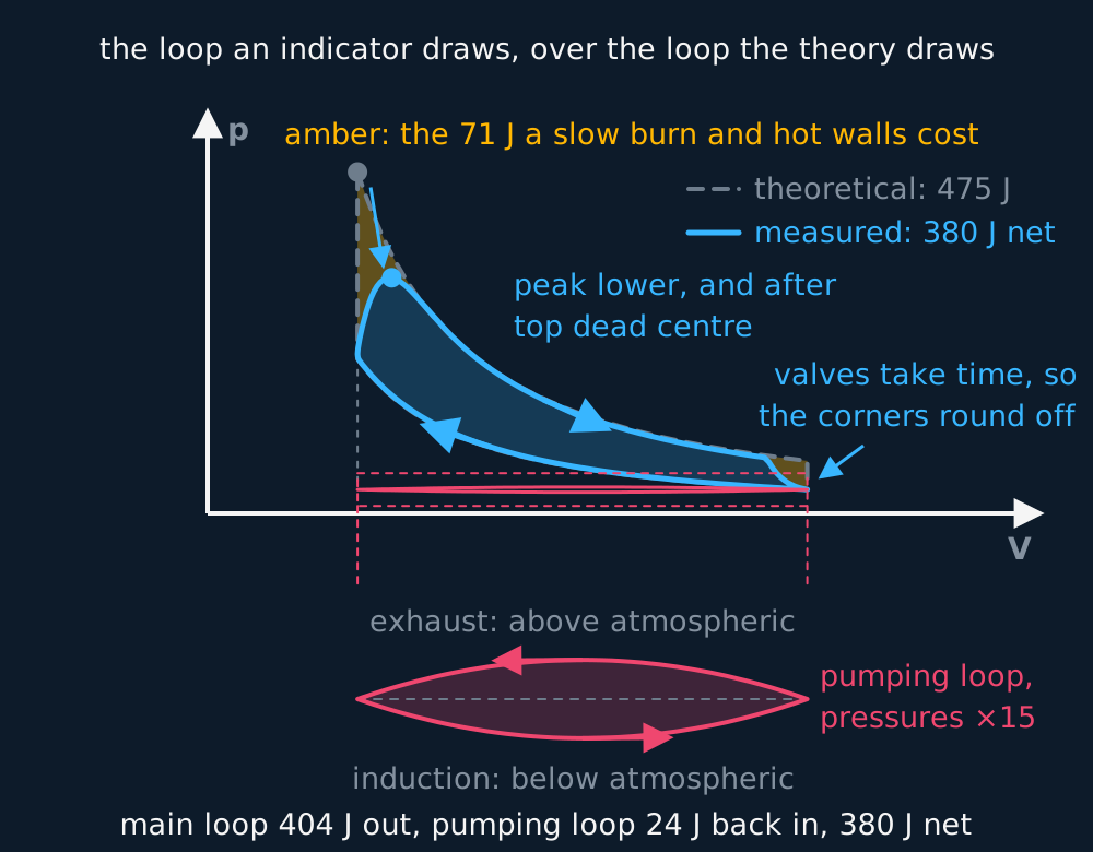
The loop a textbook draws and the loop an indicator draws are not the same shape, and every difference between them is a loss. The theoretical diagram assumes valves that open instantly, a burn that finishes instantly at the top of the stroke, compression and expansion that are reversible and adiabatic, and gas that flows in and out against no resistance. In a real cylinder the valves take time, so the sharp corners round off; the burn takes time, so the peak pressure is lower and arrives after the piston has started down; and heat leaks into the cooled walls throughout.
The bottom of the real loop also splits in two. Drawing gas in through a valve needs the cylinder slightly below atmospheric pressure, and pushing it out needs it slightly above, so the induction and exhaust strokes trace a thin loop of their own, run the other way round, whose area is work spent on breathing rather than earned. Taken together, these differences mean the real diagram encloses less area than the theoretical one, so the work per cycle is smaller, typically by a fifth, before any friction in the moving parts is counted.
Describe the drawing
Two pressure-volume loops drawn on the same axes. The theoretical cycle is a grey dashed loop with sharp corners and its pressure peak at the smallest volume. The measured loop, shaded cyan, has rounded corners and a lower peak that arrives after top dead centre, so it encloses less area. Below it, with the pressures magnified fifteen times, the induction and exhaust strokes trace a small coral loop run anticlockwise, whose area is work spent on breathing. The theoretical cycle gives 475 joules a cycle; the measured one gives 404 joules less 24 joules of pumping, so 380 joules.
Auditing a real engine
The area of the measured loop feeds a chain of powers, and the audit runs from fuel to shaft. The input power is chemical energy arriving as fuel, the fuel's calorific value (joules per kilogram) times the rate it is burned. The indicated power is what the gas develops inside the cylinders, the loop area per cycle times the cycles per second, times the number of cylinders. The brake power is what actually reaches the output shaft, measured as P = Tω. What friction and moving parts eat between cylinder and shaft is the friction power:
Those powers are also what the efficiencies are made from, and there are three to keep apart. Thermal efficiency is the indicated power divided by the input power, and it asks how much of the fuel's energy the gas in the cylinders turned into work at all. That is the W/QH of the first section rewritten as powers, so it is the one the second law caps, and no amount of engineering will take it past (TH − TC)/TH.
Mechanical efficiency is the brake power divided by the indicated power, and it asks something quite different: of the work the gas did on the pistons, how much survived the bearings, the valve gear and the oil pump to reach the shaft. No Carnot temperature ratio caps it, though energy conservation still holds it between 0 and 1, and what raises it is better lubrication rather than hotter gas.
Overall efficiency is the brake power divided by the input power, and it is the product of the other two, because the indicated power cancels between them. That product is worth writing out, since a disappointing overall figure has to be diagnosed before it can be cured: a thermal efficiency of 0.30 with a mechanical efficiency of 0.90 and a thermal 0.45 with a mechanical 0.60 both give 0.27, and they call for entirely different work.
WORKED EXAMPLE
The full audit
A four-cylinder engine has a p-V loop of area 380 J per cylinder and runs at 25 cycles per second. Its crankshaft turns at 314 rad s−1 delivering a torque of 102 N m, burning fuel of calorific value 45 MJ kg−1 at 2.0 × 10⁻³ kg s−1. Audit it.
Input power = 45 × 106 × 2.0 × 10−3 = 90 kW.
Indicated power = 380 × 25 × 4 = 38 kW. The other 52 kW left as exhaust heat and cooling, the QC of the cycle.
Brake power = Tω = 102 × 314 = 32 kW, so friction power = 38 − 32 = 6 kW.
Thermal efficiency = 38/90 = 0.42, and mechanical efficiency = 32/38 = 0.84.
Overall efficiency = 32/90 = 0.36, and (38/90) × (32/38) = 32/90 as it must, the indicated power cancelling between the two. The split is the useful part: 0.42 is thermodynamics and the second law, 0.84 is friction, and only the mechanical figure can be improved by better lubrication.
Running it backwards has moved to the next part of this lesson.
Selling the heat as well as the work has moved to the next part of this lesson.
ASSESSMENT FOCUS
- Use kelvin for both temperatures. The maximum efficiency formula is a ratio of absolute temperatures, so a Celsius value gives the wrong ratio.
- Why below 100%? Answer with the cycle. The gas must be recompressed to repeat, so heat QC must be rejected to a colder sink, so W is always less than QH. Friction is a second, separate reason, so name both when asked about a real engine.
- Give the four strokes in order (induction, compression, power, exhaust) with what each does, and put the petrol against diesel difference as what is drawn in and what lights it. Petrol compresses a fuel and air mixture about tenfold and adds its heat at constant volume after a spark; diesel compresses air alone fifteen to twenty times, hot enough to ignite the fuel injected into it, and adds its heat at constant pressure.
- Watch the factor of two in engine speed. Four strokes take two revolutions, so an engine turning at 3000 rev min−1 completes 25 cycles per second in each cylinder, not 50.
- Compare the theoretical and real indicator diagrams as a list. Rounded corners because valves and combustion take time, a lower peak pressure reached after the top of the stroke, heat lost to the cylinder walls, and a small loop at the bottom run the other way for the work of breathing. The real area, and so the real work per cycle, is smaller.
- Keep the power ladder in order (input, indicated, brake) and check each rung is smaller. Friction power is the indicated-minus-brake gap, and an answer with brake above indicated has slipped somewhere.
- Loop questions: net work per cycle is the enclosed area, clockwise for an engine, and indicated power multiplies it by cycles per second and by the number of cylinders. Include the cylinder count.
- Name the efficiency the question means. Thermal is indicated over input and is the one the second law caps; mechanical is brake over indicated and is friction; overall is brake over input and equals the other two multiplied together.
CHECK YOURSELF
In each cycle an engine absorbs 1800 J from a source at 700 K and rejects 1350 J to a sink at 315 K. Find the work per cycle, the efficiency, and the maximum theoretical efficiency, and comment on the comparison.
Show a hint
W from conservation, then two efficiency ratios, one from heats, one from kelvin temperatures.
Show the answer
W = QH − QC = 1800 − 1350 = 450 J per cycle.
Efficiency = W/QH = 450/1800 = 0.25.
Maximum = (700 − 315)/700 = 0.55. The engine achieves under half its theoretical ceiling, which is typical; the ceiling assumes a perfect, friction-free, ideally slow cycle no real engine can run.
An engine taps the flow from hot to cold: W = Q_H − Q_C, rejecting Q_C is compulsory, and the ceiling is (T_H − T_C)/T_H in kelvin.
Four strokes and two revolutions make one cycle, and the area the indicator loop encloses is the work that cycle did.
Power audit: input from fuel, indicated in the cylinders, brake at the shaft, friction the gap; thermal times mechanical is overall.
WORKBOOK
Printable practice for this topic: original exam-style questions with room to work, and a fully worked answer book. Free to use; please do not redistribute or sell.
Or read them with their mark schemes on the heat engines and their efficiency questions page.
WHERE TO GO NEXT
- Gradients and areas under graphs is the maths this lesson leans on, worked through step by step.
CHECK YOUR PROGRESS
Rate how confident you feel with each objective for this lesson. Ratings are saved in this browser, on this device, unless you sign in.
- Describe the engine cycle and calculate efficiency from W, Q_H and Q_C, and its theoretical ceiling from the kelvin temperatures.
- Explain why no heat engine can be 100% efficient, and why the ceiling rises with a hotter source or colder sink.
- Describe the four strokes of a petrol and a diesel engine, and map each onto its theoretical cycle.
- Read an indicator diagram, take the work per cycle from its area, and say how the real loop differs from the theoretical one.
- Audit a real engine with input, indicated, brake and friction power, and with thermal, mechanical and overall efficiency.
Open the full revision checklist to track your progress across the whole unit.